Spring deformation performance testing device

A testing device and deformation technology, applied in the direction of measuring devices, testing of mechanical parts, testing of machine/structural parts, etc., can solve the problems of lamp bracket breakage, light source damage, loss of anti-vibration performance, etc., and achieve low production cost and excellent structure Simple and stable effect

Inactive Publication Date: 2015-06-03
OCEANKING DONGGUAN LIGHTING TECH +2
View PDF0 Cites 5 Cited by
  • Summary
  • Abstract
  • Description
  • Claims
  • Application Information

AI Technical Summary

Problems solved by technology

[0002] In severe places, the general lamp mounting brackets do not have anti-vibration design. When the lamps are used in a relatively severe vibration environment, the mounting bracket is easily deformed in a strong vibration environment, and the light source is loose or broken, resulting in a decrease in the reliability of the lamp.
In order to ensure the reliability of the lamps and meet the requirements of customers in different vibration environments, in order to reduce the vibration energy of the lamp holder or mounting bracket, use the lamp holder or mounting bracket to simplify the vibration energy level, the commonly used method is to install the bracket or lamp holder, Or the light source is fixed and the spring is used for vibration reduction, so as to absorb vibration and reduce the vibration energy level of the outside world. Since the lamp is installed in a severe vibration environment for a long time, the spring cannot rebound after being deformed and lost due to long-term vibration and extrusion. Anti-vibration performance, thus causing common failures such as lamp bracket breakage, or light source damage, thereby reducing the reliability index of the product
In the prior art, the spring test device can only realize the test of a single length spring, and the versatility is poor

Method used


Image

  • Spring deformation performance testing device
  • Spring deformation performance testing device
  • Spring deformation performance testing device

Examples


Embodiment Construction

[0023] The following will clearly and completely describe the technical solutions in the embodiments of the present invention with reference to the drawings in the embodiments of the present invention.

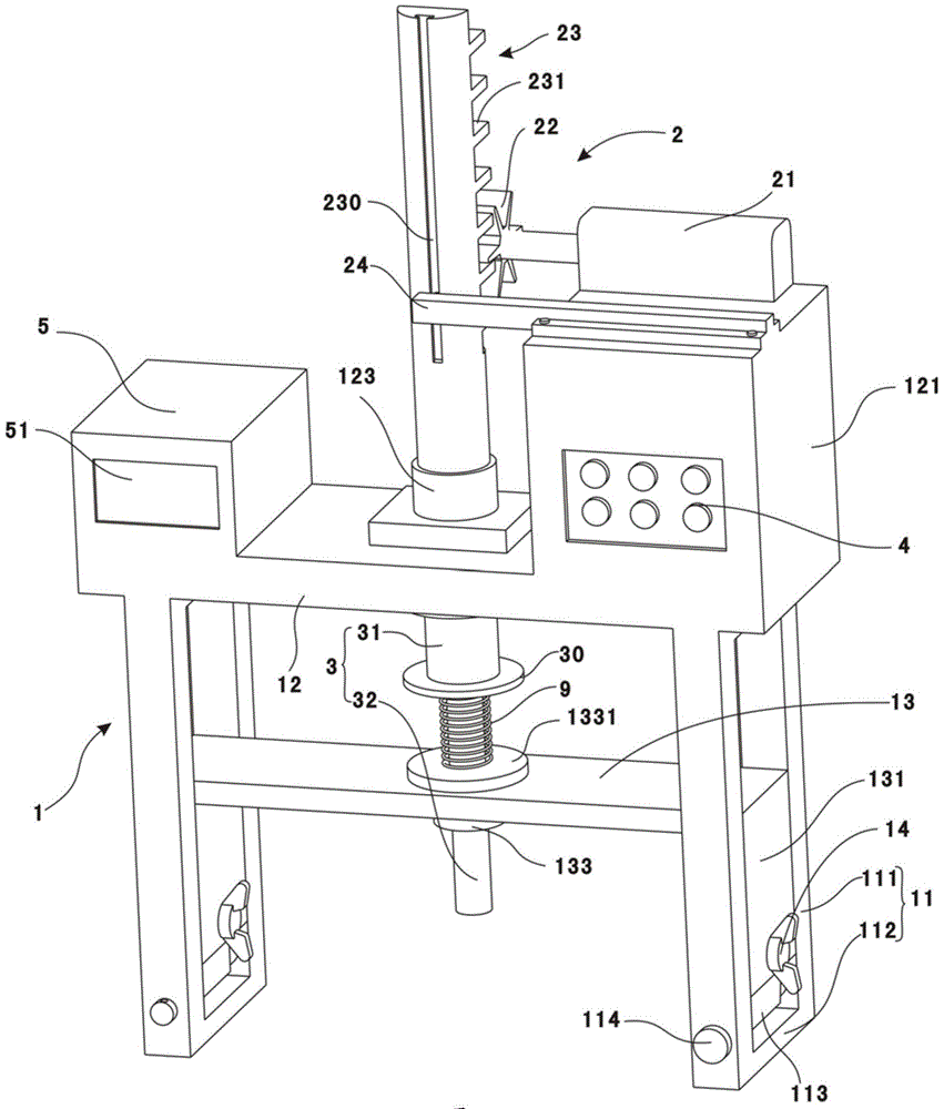
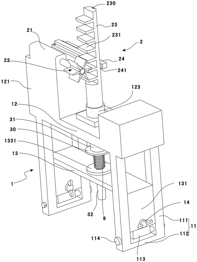
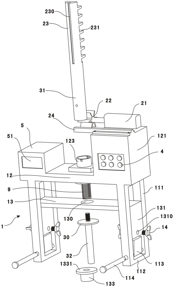
[0024] Please also refer to Figure 1 to Figure 4 , a spring deformation performance test device provided by the embodiment of the present invention includes a bracket 1, a drive assembly 2 and a slide bar 3; the drive assembly 2 and the slide bar 3 are both connected to the bracket 1, and the drive assembly 2 is connected to the slide bar 3 to drive The slide bar 3 reciprocates linearly along the axial direction of the slide bar 3 relative to the support 1 , and the slide bar 3 can drive the tested spring 9 to expand and contract to test the deformation performance of the spring.

[0025] The bracket 1 includes a supporting part 11 , a fixing part 12 and a supporting part 13 . The fixing part 12 is fixedly connected to the supporting part 11 . The bearing member 13 is space...


PUM


Abstract

The invention discloses a spring deformation performance testing device. The spring deformation performance testing device comprises a support, a driving assembly and a sliding rod, wherein the support comprises supporting pieces, a fixing piece and a bearing piece; the sliding rod slidably penetrates through the fixing piece and the bearing piece; each supporting piece is rectangular frame-shaped, and the supporting pieces comprise two long frame sides and two short frame sides; the bearing piece and the fixing piece are arranged at interval; sliding blocks are arranged on the bearing piece, and the sliding blocks are slidably arranged between the two long frame sides; the driving assembly is used for driving the sliding rod to linearly move back and forth. A spring to be tested can sleeve the sliding rod and be located between a pressing portion and the bearing piece, and a space for spring testing can be formed between the fixing piece and the bearing piece; by sliding the sliding blocks in the frame-shaped supporting pieces and locking the sliding blocks through locking bolts, the adjustment of the position of the bearing piece relative to the supporting pieces can be realized, and thus the space between the fixing piece and the bearing piece is adjusted to install springs with different length; since the supporting pieces are frame-shaped, the stability is good and the sliding fitting with the sliding blocks is facilitated.

Description

technical field [0001] The invention relates to spring reliability testing, in particular to a spring deformation performance testing device. Background technique [0002] In severe places, the general lamp mounting brackets do not have anti-vibration design. When the lamps are used in a relatively severe vibration environment, the mounting bracket is easily deformed in a strong vibration environment, and the light source is loose or broken, resulting in a decrease in the reliability of the lamp. In order to ensure the reliability of the lamps and meet the requirements of customers in different vibration environments, in order to reduce the vibration energy of the lamp holder or mounting bracket, use the lamp holder or mounting bracket to simplify the vibration energy level, the commonly used method is to install the bracket or lamp holder, Or the light source is fixed and the spring is used for vibration reduction, so as to absorb vibration and reduce the vibration energy l...

Claims


Application Information

Patent Timeline
Patent Type & Authority Applications(China)
IPC IPC(8): G01M13/00G01N3/00
Inventor 周明杰胡波
Owner OCEANKING DONGGUAN LIGHTING TECH
Why Eureka
Try Eureka