
Adaptive interference cancellation method for radar jammer

A technology of radar interference and interference cancellation, applied in the direction of instruments, radio wave measurement systems, etc., can solve the problems of reducing the reconnaissance distance, increasing the transceiver isolation of the jammer, and increasing the lateral radiation of the transceiver antenna. Convergence speed, achieve convergence stability, achieve the effect of compromise

Inactive Publication Date: 2015-06-03
HOHAI UNIV
View PDF3 Cites 26 Cited by
  • Summary
  • Abstract
  • Description
  • Claims
  • Application Information

AI Technical Summary

Problems solved by technology

During the jamming process, the layout of the jamming system is subject to various restrictions due to the combat environment, or the platform of the airborne jammer, the distance between the transmitting and receiving antennas cannot be large enough, and the jamming signal may be directly coupled in space or pass through The emission of surrounding close-range environmental objects forms multi-path signals into the reconnaissance receiver of the jammer, which may lead to a reduction in the actual sensitivity of the reconnaissance receiver and a reduction in the reconnaissance range; Unable to detect radar signal
[0007] Traditional methods to improve transceiver isolation, such as increasing the distance between transceiver antennas, reducing the lateral radiation of transceiver antennas, and adding orthogonal absorptive isolation screens between transceiver antennas, cannot meet the high isolation requirements of small platform jammers. , so it is necessary to find a method to effectively weaken the impact of jamming signals on the reconnaissance receiving system. Increasing the isolation of jammers from transceivers is an important problem that needs to be solved urgently in forward jamming technology

Method used


Image

  • Adaptive interference cancellation method for radar jammer
  • Adaptive interference cancellation method for radar jammer
  • Adaptive interference cancellation method for radar jammer

Examples


Embodiment Construction

[0027] The specific implementation manners of the present invention will be further described in detail below in conjunction with the accompanying drawings.

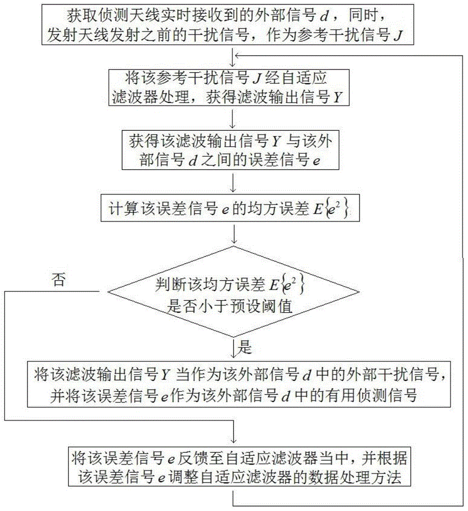
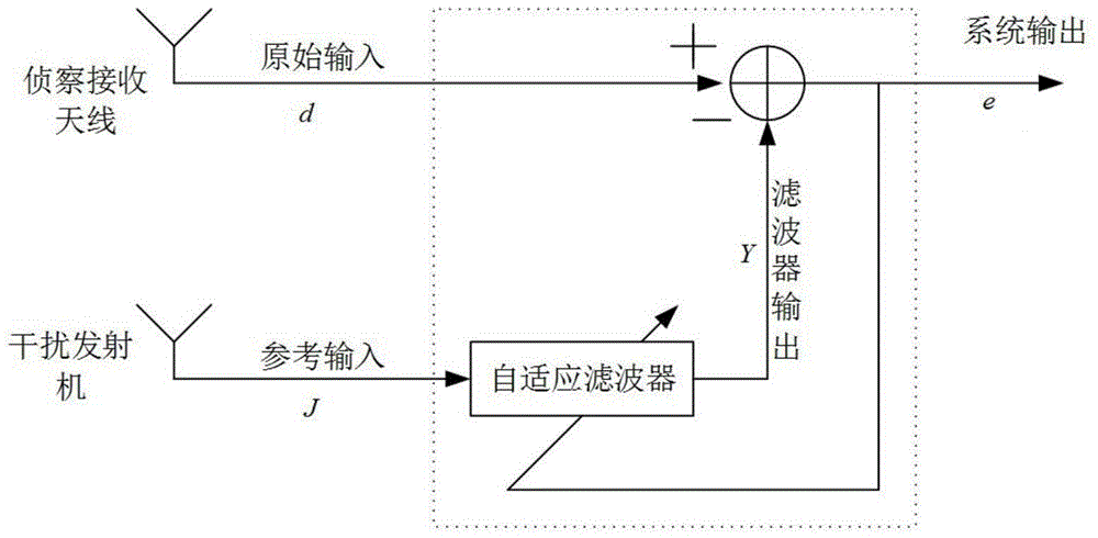
[0028] Such as figure 1 and figure 2 As shown, the present invention designs a radar jammer adaptive interference cancellation method. In the actual application process, a digital delay adaptive filter is set in the radar jammer, and the weight vector W in the digital delay adaptive filter is defined as W=[w 0 ,w 1 ,...,w j ] T , where w j Be the weight of the jth receiving antenna on the radar jammer, T is the conjugate transposition of the weight vector W, and initialize the weight vector and the iterative convergence step coefficient, and the adaptive interference cancellation method includes the following steps:

[0029] Step 001. Obtain the external signal d received by the detection antenna on the radar jammer in real time, and at the same time, obtain the interference signal generated in the radar jammer an...


PUM


Abstract

The invention relates to an adaptive interference cancellation method for a radar jammer. The adaptive interference cancellation method comprises the following steps: acquiring an external signal d received by a detection antenna on the radar jammer in real time, simultaneously acquiring an interference signal which is generated in the radar jammer and is not transmitted by a transmitting antenna of the radar jammer and using the interference signal as a reference interference signal J; then conveying the external signal d and the reference interface signal J to an adaptive filter to carry out adaptive interference cancellation. According to the adaptive interference cancellation method, an active digital adaptive cancellation technology is adopted; related cancellation principles are utilized; a convergence step size is regulated; compromise of a convergence rate and convergence stability in an adaptive interference cancellation algorithm is effectively realized; finally, the interference signal entering the detection antenna can be effectively eliminated and a useful detection signal is obtained.

Description

technical field [0001] The invention relates to a method for self-adaptive interference cancellation of a radar jammer, and relates to a method for solving the problem of isolation of transmission and reception of interference equipment that needs to work simultaneously in detection and transmission on a miniaturized platform. Background technique [0002] The reconnaissance of radar radiation sources is the premise of effective electronic jamming. The reconnaissance receiver is used to receive the radar signal emitted by the enemy, to find the existence of the enemy's radar, and to quickly measure its related parameters and identify the threat level of the radar to guide the jamming The aircraft jams and destroys enemy radars. The detection and reception of radar signals is the basis of radar countermeasures, the prerequisite for seizing electromagnetic superiority and the key to defeating the enemy. [0003] The interference emitted by the jammer itself does not affect th...

Claims


Application Information

Patent Timeline
Patent Type & Authority Applications(China)
IPC IPC(8): G01S7/292G01S7/35
CPCG01S7/38
Inventor 麻清华蒋德富
Owner HOHAI UNIV
Learn More