
System and method for monitoring an aircraft engine

Pending Publication Date: 2022-08-04
SAFRAN
View PDF0 Cites 1 Cited by
  • Summary
  • Abstract
  • Description
  • Claims
  • Application Information

AI Technical Summary

Benefits of technology

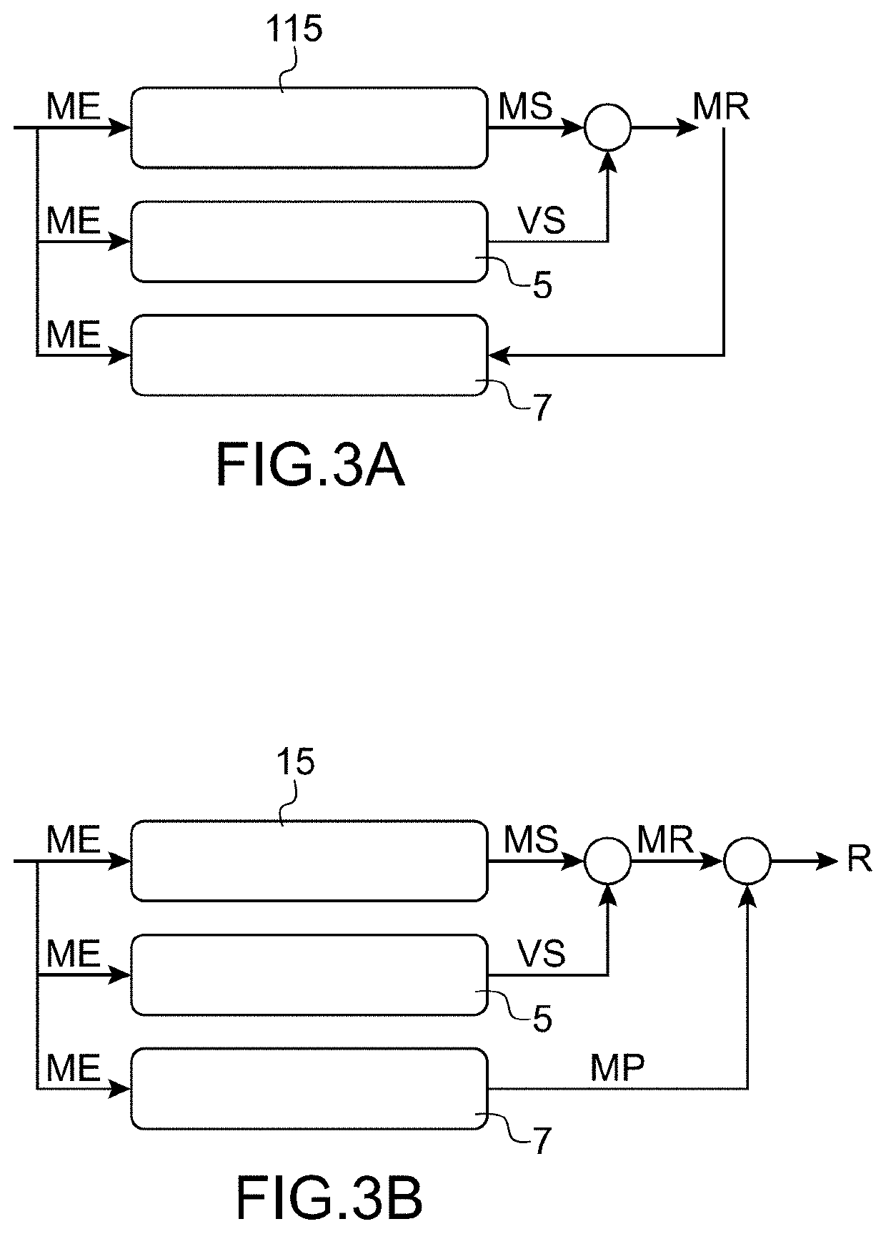
This patent is about a system that combines the simulation module and the learning module to create a synergy that can use the physical model in a new way. This allows the model to predict data outside its normal operating mode and makes better use of the data. By taking into account the transient or unstable phases, the system can automatically perform trend tracking and react faster to anomalies. By using a reference aircraft engine and selecting a number of learning flights, the learning module can accurately predict the components' margin. This increases the learning efficiency while maintaining high accuracy.

Problems solved by technology

However, these margins remain valid only on those parts for which the physical model remains valid, and thus suffer from the limitation of the monitoring operating range.
Further, due to a small amount of data in the stable phases, it is sometimes necessary for a pilot to perform flights entirely dedicated to the calculation of margins, which represents additional workload and cost.

Method used


Image

  • System and method for monitoring an aircraft engine
  • System and method for monitoring an aircraft engine
  • System and method for monitoring an aircraft engine

Examples


Embodiment Construction

[0041]The principle of the invention consists in coupling a physical model of the behaviour of the aircraft engine with a learning model so that usage of the measurements acquired during flights is maximised, thus allowing a complete and optimal tracking of the engine.

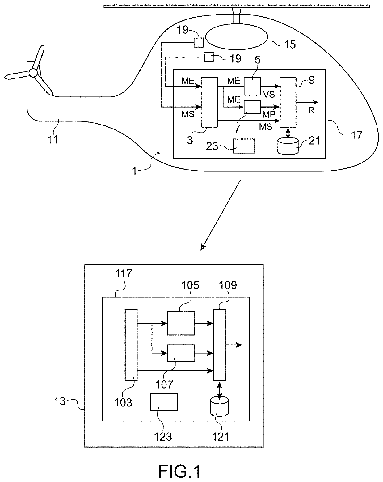
[0042]FIG. 1 schematically illustrates a system for monitoring an aircraft engine according to one embodiment of the invention.

[0043]The monitoring system 1 includes an acquisition module 3, a simulation module 5, a learning module 7 and a processor 9.

[0044]The monitoring system 1 may be entirely included in an aircraft 11 or shared between the aircraft 11 and a maintenance centre 13.

[0045]The aircraft 11 (here represented by a helicopter but may be an aeroplane) comprises an engine 15, an on-board computer 17 and sensors 19.

[0046]The sensors 19 measure physical quantities, referred to as physical input quantities and physical output quantities, relating to the aircraft engine 15 and its environment.

[0047]By way of exa...


PUM


Abstract

A system for monitoring an aircraft engine, including an acquisition module for acquiring current measurements of physical quantities, referred to as input and output physical sizes, relative to the aircraft engine, a module for simulating the physical behavior of the aircraft engine, in order to simulate output physical quantities as a function of the current measurements of input physical sizes, a processor for calculating physical margins, referred to as actual physical margins, between the simulated values of output physical quantities and the corresponding current measurements of output physical quantities, a learning module for predicting margins, the margins being predicted using current measurements of input physical quantities and wherein the processor is configured to calculate surveillance residuals giving an indication of the state of the aircraft engine.

Description

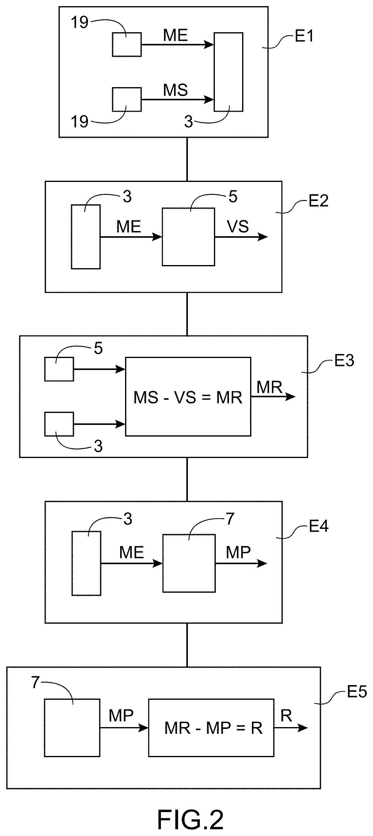
TECHNICAL FIELD[0001]The present invention is concerned with the field of monitoring an aircraft engine. In particular, the invention relates to a monitoring method and system for tracking the state of the engine in order to anticipate maintenance operations.[0002]The term “aircraft engine” refers to all turbine engines fitted to flying aircraft, especially helicopters and aeroplanes.STATE OF PRIOR ART[0003]Currently, the state of aircraft engines, and in particular helicopter engines, is tracked by calculating margins or indicators during specific manoeuvres referred to as Engine Power Check (EPC). The margins are calculated using a physical model that simulates the thermodynamic behaviour of the engine. More particularly, the model receives as inputs data relating to engine and flight conditions and outputs estimated data from the input data. The variables in the output data are also recorded in real time by sensors so that margins are calculated by subtracting the estimates from ...

Claims


Application Information

Patent Timeline
IPC IPC(8): B64F5/60G01M15/14G07C5/08
CPCB64F5/60G01M15/14B64C27/04G07C5/0841G07C5/0808B64F5/40B64D2045/0085B64D45/00G05B17/02G07C5/008
Inventor RAZAKARIVONY, SÉBASTIEN PHILIPPE
Owner SAFRAN
Learn More