
Light emitting device and light emitting device package

A light-emitting device packaging and light-emitting device technology, which is applied in the direction of electric solid-state devices, semiconductor devices, electrical components, etc., can solve the problems affecting the light extraction rate of light-emitting devices, so as to improve the light-emitting performance, increase the light-extraction rate, and avoid absorption and shading Effect

Inactive Publication Date: 2015-06-03
TCL CHINA STAR OPTOELECTRONICS TECH CO LTD
View PDF2 Cites 0 Cited by
  • Summary
  • Abstract
  • Description
  • Claims
  • Application Information

AI Technical Summary

Problems solved by technology

[0003] In the prior art, light-emitting devices such as LED light-emitting chips are usually lead from the light-emitting surface to connect the positive and negative electrodes. However, the lead itself will absorb and block the light emitted by the light-emitting device, which affects the light extraction rate of the light-emitting device.

Method used


Image

  • Light emitting device and light emitting device package
  • Light emitting device and light emitting device package
  • Light emitting device and light emitting device package

Examples


Embodiment Construction

[0035] The following will clearly and completely describe the technical solutions in the embodiments of the present invention with reference to the accompanying drawings in the embodiments of the present invention. Obviously, the described embodiments are only some, not all, embodiments of the present invention. Based on the embodiments of the present invention, all other embodiments obtained by persons of ordinary skill in the art without creative efforts fall within the protection scope of the present invention.

[0036] It should be noted that the terms used in the embodiments of the present invention are only for the purpose of describing specific embodiments, and are not intended to limit the present invention. As used in the embodiments of the present invention and the appended claims, the singular forms "a", "said" and "the" are also intended to include the plural forms unless the context clearly indicates otherwise. It should also be understood that the term "and / or" u...


PUM


Abstract

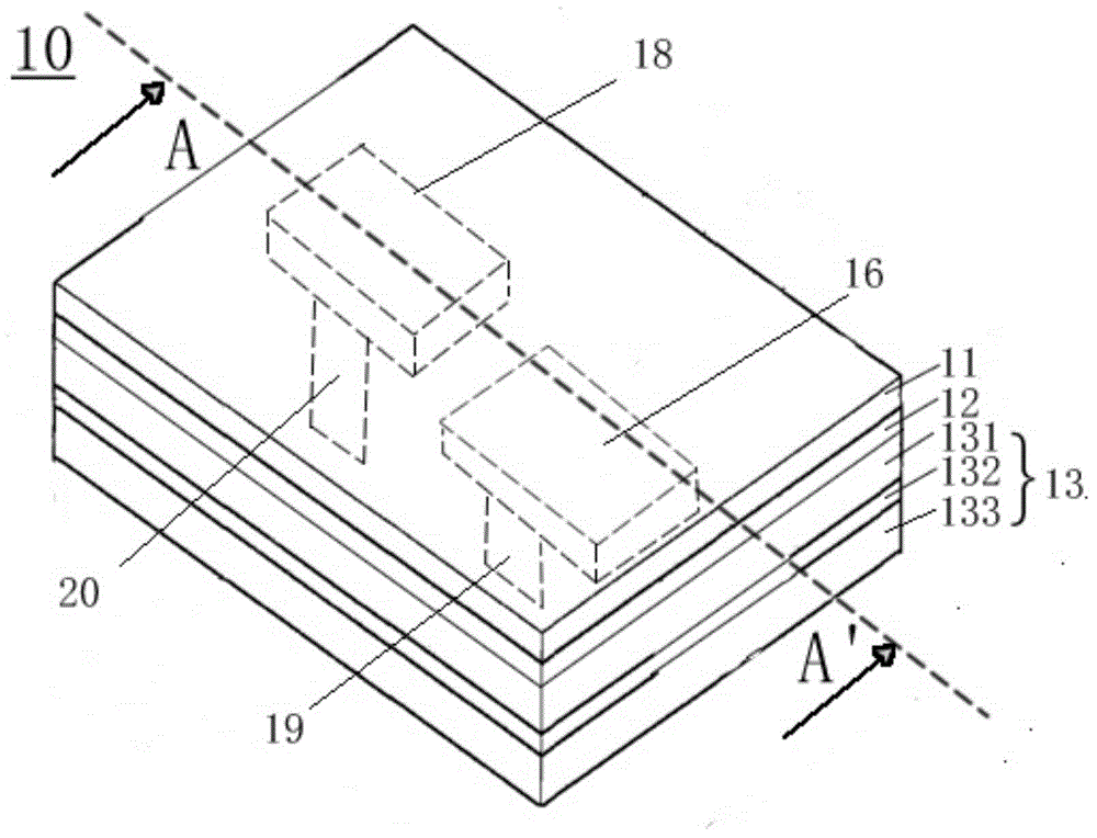
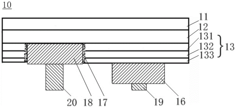
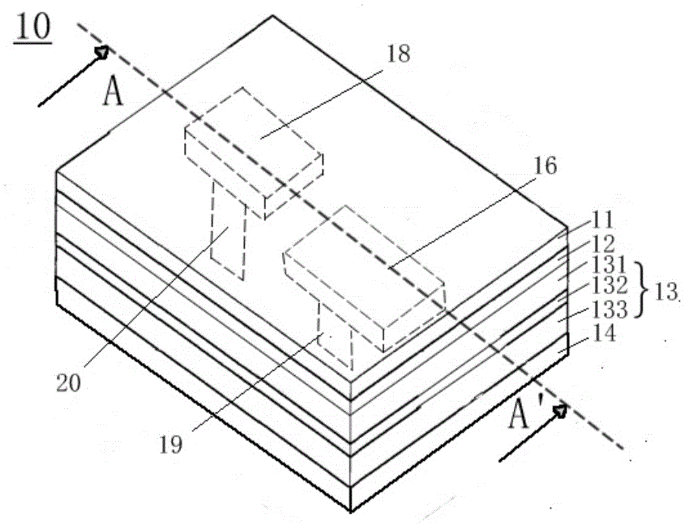
The embodiment of the invention discloses a light emitting device and a light emitting device package. The light emitting device comprises a light emitting structure, wherein the light emitting structure comprises a first conduction type semiconductor layer, an active layer, a second conduction type semiconductor layer, a first electrode, a first electrode layer, a second electrode and an insulating layer, the first conduction type semiconductor layer, the active layer and the second conduction type semiconductor layer are stacked in sequence, the second conduction type semiconductor layer is used as a light-out surface of the light emitting structure, the first electrode is arranged on the surface, which is far from the active layer, of the first conduction type semiconductor layer, the first electrode is electrically connected with the first conduction type semiconductor layer, the first electrode layer is arranged on the surface, which is far from the active layer, of the second conduction type semiconductor layer, the first electrode layer is electrically connected with the second conduction type semiconductor layer, the second electrode penetrates through the light emitting structure and is electrically connected with the first electrode layer, and the insulating layer is arranged between the light emitting structure and the second electrode. By adopting the light emitting device, the electrodes are led out from the bottom of the light emitting device, so that light is prevented from being shielded and absorbed by leading wires, and the light-out rate is increased.

Description

technical field [0001] The invention relates to the field of light emitting devices, in particular to a light emitting device and a package of the light emitting device. Background technique [0002] The sustainable use of energy has always been the focus of social attention. Scientists are developing various low-energy, high-performance light-emitting tubes to alleviate the current energy pressure. Among them, light-emitting diodes (Light-Emitting Diode, referred to as LED) are highly efficient The effect of energy saving is outstanding, and it is constantly being popularized in various fields of life. [0003] In the prior art, light-emitting devices such as LED light-emitting chips are usually lead from the light-emitting surface to connect the positive and negative electrodes. However, the lead itself will absorb and block the light emitted by the light-emitting device, affecting the light extraction rate of the light-emitting device. Contents of the invention [0004...

Claims


Application Information

Patent Timeline
IPC IPC(8): H01L33/36H01L33/60H01L33/58
CPCH01L33/382H01L33/405H01L2224/16245H01L33/36H01L33/10H01L33/22H01L33/38H01L33/46H01L33/62
Inventor 程艳周革革
Owner TCL CHINA STAR OPTOELECTRONICS TECH CO LTD
Features
  • Generate Ideas
  • Intellectual Property
  • Life Sciences
  • Materials
  • Tech Scout
  • Unparalleled Data Quality
  • Higher Quality Content
  • 60% Fewer Hallucinations
Learn More