A Radar Antenna Array Element Multi-frequency Matching Method

An antenna array element and radar antenna technology, applied in antenna arrays, antennas, electrical components and other directions, can solve the problems of radar antenna scientific research, production manpower, material resources, financial resources, shorten the development and production cycle, etc., to shorten the development, save Manpower, the effect of reducing plugging time

Active Publication Date: 2018-01-12
LEIHUA ELECTRONICS TECH RES INST AVIATION IND OF CHINA
View PDF6 Cites 0 Cited by
  • Summary
  • Abstract
  • Description
  • Claims
  • Application Information

AI Technical Summary

Problems solved by technology

[0004] Purpose of the invention: The present invention proposes a new method for radar antenna element matching to solve the problem of requiring a large amount of manpower, material resources and financial resources in the process of radar antenna scientific research and production, and greatly shorten the development and production cycle

Method used


Image

  • A Radar Antenna Array Element Multi-frequency Matching Method

Examples


Embodiment

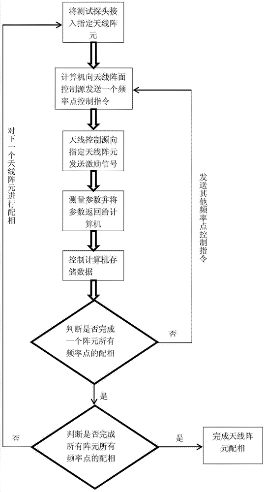
[0023] Example: For 1000 array elements, each array element has 25 frequency points for matching.

[0024] A radar antenna array element multi-frequency point matching method, comprising the following steps:

[0025] Step 1: Connect the test probe to the designated antenna element;

[0026] Step 2: The control computer sends control information corresponding to a frequency point of the designated antenna element to the array control source, and the array control source generates an excitation signal for the designated antenna array element after receiving this information, and the corresponding antenna array element After receiving the excitation signal, the corresponding phase is generated;

[0027] Step 3: Use a vector network analyzer to measure the data of the corresponding frequency point, and transmit it to the control computer through the GPIB cable;

[0028] Step 4: The control computer receives the data at this frequency point and performs corresponding data process...


PUM


Abstract

The invention belongs to the field of microwave measurement, and relates to a method for multi-frequency point matching of radar antenna array elements, which includes the following steps: Step 1: Connect a test probe to a designated antenna array element; The source sends the control information corresponding to a frequency point of the specified antenna element; Step 3: Measure the data of the corresponding frequency point with a vector network analyzer, and transmit it to the control computer through the GPIB cable; Step 4: The control computer receives the data at this frequency point The data is stored in the corresponding database after corresponding data processing. Step 5: Judging whether the matching of all frequency points of an array element is completed; Step 6: Judging whether matching of all frequency points of all array elements is completed. The number of times of plugging and unplugging at each frequency point is greatly reduced, thereby reducing the plugging and unplugging time of the entire matching cycle, saving manpower, material resources, and financial resources in the matching process, and greatly shortening the development and production cycle.

Description

technical field [0001] The invention belongs to the field of microwave measurement and relates to a multi-frequency point matching method for radar antenna array elements. Background technique [0002] In the development and production process of the phased array radar antenna, it is necessary to carry out phase matching work for each array element in the radar antenna, so that each array element can work according to a certain working phase. In the phase matching process, for a certain characteristic frequency point, all the phase shifters complete a phase matching, which is called completing a phase matching cycle. Since the radar needs to work with multiple frequency points, it is necessary to perform multi-frequency point matching for all array elements in the front. However, in the traditional matching method, only one frequency point can be matched in one matching cycle, which leads to too long matching time and extremely low matching efficiency. [0003] From an eco...

Claims


Application Information

Patent Timeline
Patent Type & Authority Patents(China)
IPC IPC(8): H01Q3/30H01Q21/00
Inventor 雷鸣郑慧敏黄宏卫
Owner LEIHUA ELECTRONICS TECH RES INST AVIATION IND OF CHINA
Why Eureka
Try Eureka