Self-interference elimination method of full duplex system

A self-interference cancellation, full-duplex technology, applied in transmission systems, duplex signal operations, electrical components, etc., can solve the problem of inability to demodulate the required information, low transmission efficiency, and difficulty in effectively eliminating the full-duplex system of spatial modulation Self-interference, etc.

Active Publication Date: 2015-06-03
PEKING UNIV
View PDF5 Cites 10 Cited by
  • Summary
  • Abstract
  • Description
  • Claims
  • Application Information

AI Technical Summary

Problems solved by technology

However, like ordinary full-duplex, spatial modulation full-duplex is also subject to strong self-interference, and the existing self-interference cancellation method requires additional self-interference channel estimation,

Method used


Image

  • Self-interference elimination method of full duplex system
  • Self-interference elimination method of full duplex system
  • Self-interference elimination method of full duplex system

Examples


Embodiment 1

[0054] In the case of two time slots, for each full-duplex node, the following steps are included:

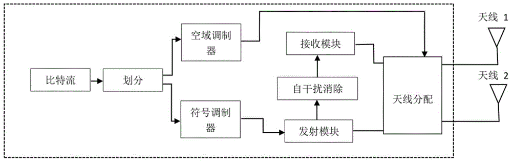
[0055] 1) For the airspace modulation full-duplex system, the information bit stream is divided into two parts, one part of the information is used to control the airspace modulator to determine which antenna is the transmitting antenna and the receiving antenna in the node, and the other part of the information is encoded And send it to the symbol modulator; for traditional full-duplex systems, this step is not required;

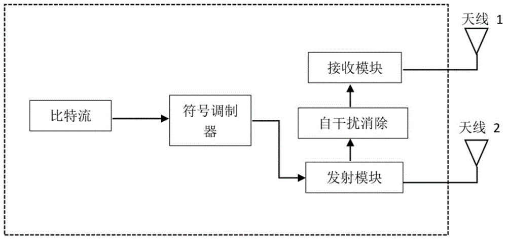
[0056] 2) The information sent to the symbol modulator is modulated to the corresponding constellation point of the symbol modulator, and after the modulation is completed, it is sent to the transmitting module for transmission;

[0057] 3) The transmitting module shares the transmitted content with the receiving module;

[0058] 4) The receiving module uses the transmitted content information shared by the transmitting module to eliminate self-interference...

Embodiment 2

[0066] In the case of three time slots, for each full-duplex node, the following steps are included:

[0067] 1) For the airspace modulation full-duplex system, the information bit stream is divided into two parts, one part of the information is used to control the airspace modulator to determine which antenna is the transmitting antenna and the receiving antenna in the node, and the other part of the information is encoded And send it to the symbol modulator; for traditional full-duplex systems, this step is not required;

[0068] 2) The information sent to the symbol modulator is modulated to the corresponding constellation point of the symbol modulator, and after the modulation is completed, it is sent to the transmitting module for transmission;

[0069] 3) The transmitting module shares the transmitted content with the receiving module;

[0070] 4) The receiving module uses the transmitted content information shared by the transmitting module to eliminate self-interferen...


PUM


Abstract

The invention discloses a self-interference elimination method of a full duplex system. Each full duplex node comprises a symbol modulator, a sending module, a receiving module and two antennae, wherein the data of the multiple continuous time slots are collected for algebraic operation so as to eliminate self-interference by virtue of the receiving module of the node, after a converted receiving signal is obtained, the signal is demodulated by virtue of a maximum likelihood method. The sending module can send a symbol by virtue of a method of a constellation point of a rotating symbol modulator, a demodulation mistake of an inherent mode during a process of demodulating the converted receiving signal is avoided. The self-interference elimination method not only can be used in a common full duplex system, but also can be used in an airspace modulation full duplex system, the self-interference is eliminated by virtue of the self-interference elimination method, and the estimation of a self-interference communication channel is not carried out; the signal-to-noise ratio is improved, the equipment cost is lowered, the communication efficiency is improved, and the self-interference elimination method has great economic value for a communication equipment manufacturer and a communication operator.

Description

technical field [0001] The invention relates to mobile communication technology, in particular to a self-interference elimination method of a full-duplex system. Background technique [0002] In the field of wireless communication, full-duplex (FD, Full Duplex) technology means that a communication node sends and receives data in the same frequency band at the same time, which has higher spectral efficiency than the traditional half-duplex mode. The main problem with full-duplex is that each communicating node will experience extremely strong self-interference. Specifically, the wireless signal attenuates with the increase of the distance, and the signal of the local transmitting antenna will be much higher than that of other node transmitting antennas, so that it is difficult to demodulate the information from other transmitting nodes. [0003] For full-duplex systems, the existing self-interference cancellation method in the digital domain is to directly estimate the self...

Claims


Application Information

Patent Timeline
IPC IPC(8): H04B1/525H04L5/14
Inventor 程翔鞠培中温淼文
Owner PEKING UNIV
Why Eureka
Try Eureka