LED (Light-emitting Diode) drive circuit and mine explosion-proof lamp

A technology of LED driver and LED module, applied in the field of lighting, can solve the problem of low security of the driving circuit, and achieve the effect of enhancing portability, high security and enhancing security.

Active Publication Date: 2015-06-03
SHENZHEN OCEANS KING LIGHTING ENG CO LTD +1
View PDF5 Cites 1 Cited by
  • Summary
  • Abstract
  • Description
  • Claims
  • Application Information

AI Technical Summary

Problems solved by technology

[0004] The purpose of the present invention is to provide a LED driving circuit, aiming to solve the problem of low safety of the driving circuit in the existing mine explosion-proof mine explosion-proof lamps

Method used


Image

  • LED (Light-emitting Diode) drive circuit and mine explosion-proof lamp
  • LED (Light-emitting Diode) drive circuit and mine explosion-proof lamp
  • LED (Light-emitting Diode) drive circuit and mine explosion-proof lamp

Examples


Embodiment 1

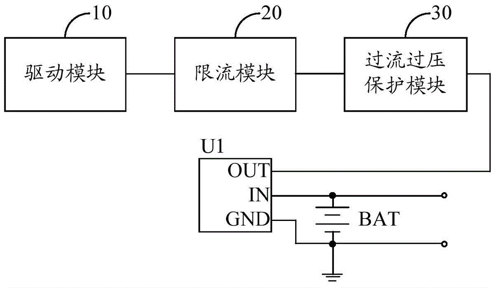
[0020] figure 1 The circuit structure of the LED driving circuit provided by this embodiment is shown. For the convenience of description, only the parts related to this embodiment are shown, and the details are as follows:

[0021] The LED driving circuit provided in this embodiment includes a driving module 10 connected to an LED module and driving the LED module to work.

[0022] Further, the LED driving circuit also includes a mine battery protector U1 , a battery BAT, a current limiting module 20 and an overcurrent and overvoltage protection module 30 .

[0023] Specifically, the positive pole of the storage battery BAT is connected with the input terminal of the mine battery protector U1 to form the positive charging terminal of the LED drive circuit, and the negative pole of the battery BAT is connected with the ground terminal of the mine battery protector U1 to form the negative terminal of the LED drive circuit. The charging terminal is connected to the ground;

[...

Embodiment 2

[0053] In this example, if Figure 4 As shown, the current limiting module 20 includes:

[0054] The fifth diode D5, the sixth diode D6 and the twelfth resistor R12;

[0055] The cathode of the fifth diode D5 is connected to the anode of the sixth diode D6, the cathode of the sixth diode D6 is connected to the first end of the twelfth resistor R12, and the input end of the fifth diode D5 is a current limiting module 20 and the second end of the twelfth resistor R12 is the input end of the current limiting module 20 .

[0056] In this embodiment, since the diode is not a reliable component, the resistor is a reliable component. A resistor can be used to replace one of the diodes in the previous embodiment, so that there is a reliable component in the circuit to limit the current. When unreliable components fail, there are reliable components to protect, so as to avoid coal mine fire or explosion.

[0057] Specifically, the twelfth resistor R12 may be a metal film resistor o...

Embodiment 3

[0059] The implementation of this embodiment is based on the foregoing embodiments.

[0060] In this embodiment, the LED driving circuit may further include a seventh diode;

[0061] The cathode of the seventh diode is connected to the positive pole of the storage battery, and the anode is the second positive charging terminal of the LED driving circuit.

[0062] In this embodiment, the battery BAT can be charged through the second positive charging terminal and the negative charging terminal of the LED driving circuit. The added seventh diode can make the LED driving circuit safer during charging, and avoid damage to electronic components inside the LED driving circuit caused by unstable charging current.


PUM


Abstract

The invention belongs to the technical field of illumination and particularly relates to an LED (Light-emitting Diode) drive circuit and a mine explosion-proof lamp. The LED drive circuit provided by the invention comprises a drive module, a mine battery protector, a storage battery, a current-limiting module and an overcurrent and overvoltage protection module. According to the LED drive circuit, electric energy stored in the storage battery is utilized for supplying power to the whole LED drive circuit, and the mine battery protector is adopted to protect the battery, so that the battery is prevented from the phenomena such as overvoltage, undervoltage, overcurent or short circuit; in addition, the overcurrent and overvoltage protection module is utilized to disconnect a power supply loop under a condition that overcurrent and overvoltage occur; meanwhile, diodes in the current-limiting module are utilized to limit currents output by the storage battery; furthermore, the drive module only outputs currents which are less than one third of the rated working current of an LED module. Since the whole circuit has high safety, the mine explosion-proof lamp adopts a light shell, so that the portability of the mine explosion-proof lamp is enhanced.

Description

technical field [0001] The invention belongs to the technical field of lighting, and in particular relates to an LED driving circuit and an explosion-proof lamp for mine use. Background technique [0002] Currently used mine explosion-proof lamps generally adopt very thick metal walls plus transparent parts with a thickness of several centimeters to make the lamp housing. The reason is that there are many combustible gases in the mine, and the driving circuit of ordinary lamps will inevitably fail, resulting in an explosion and fire, thereby igniting the combustible gas outside the lamp. Therefore, in order to make up for the lack of safety of the driving circuit of the lamp, a thick casing is used to isolate the driving circuit from the combustible gas outside, so that even if the electronic components inside the lamp explode and catch fire, the combustible gas outside the lamp casing will not be ignited. So as to achieve the effect of explosion-proof. Adopting such an ex...

Claims


Application Information

Patent Timeline
Patent Type & Authority Applications(China)
IPC IPC(8): H05B37/02
Inventor 周明杰刘百顺
Owner SHENZHEN OCEANS KING LIGHTING ENG CO LTD
Why Eureka
Try Eureka