Electric pump

An electric pump and motor technology, applied in electric components, pumps, brakes, etc., can solve the problem of wiring harnesses and connectors, and achieve the effect of ensuring installation space

Active Publication Date: 2015-06-03
MIKUNI CORP
View PDF7 Cites 1 Cited by
  • Summary
  • Abstract
  • Description
  • Claims
  • Application Information

AI Technical Summary

Problems solved by technology

The configuration in which the installation space of the electrical structure disclosed in Patent Document 2 is limited cannot fully cope with the above-mentioned various requirements.
[0009] Therefore, it is conceivable to provide a connector on the cover portion on the opposite side of the motor as in the structure disclosed in Patent Document 1, but the structure shown in Patent Document 1 is a structure in which a flexibly movable wiring harness is passed through the wiring hole, It is necessary to pull out the wiring harness from the wiring hole, and it takes time to connect the wiring harness to the connector.

Method used


Image

  • Electric pump
  • Electric pump
  • Electric pump

Examples


Embodiment Construction

[0049] Hereinafter, an electric pump according to an embodiment of the present invention will be described with reference to the drawings.

[0050]

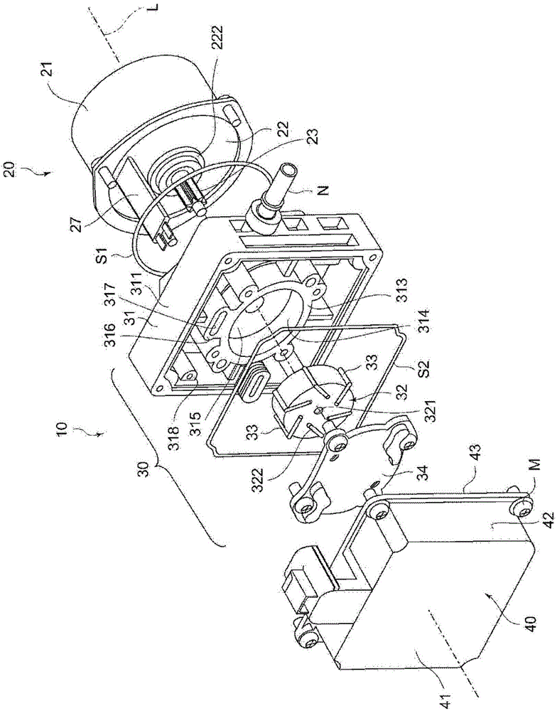
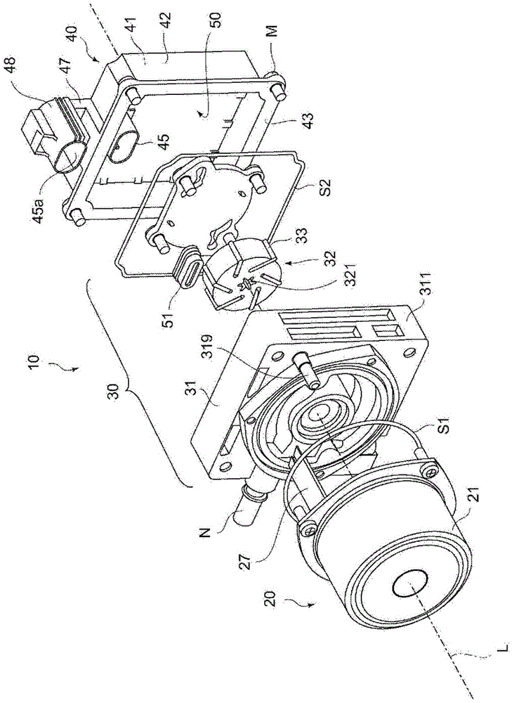
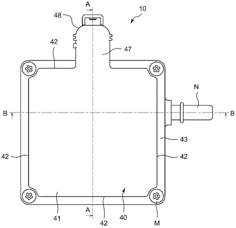
[0051] figure 1 It is an exploded perspective view showing the structure of the electric pump 10 viewed from the pump cover 40 side, figure 2 It is an exploded perspective view showing the configuration of the electric pump 10 viewed from the motor unit 20 side. in addition, image 3 It is a front view showing the configuration of the electric pump 10 viewed from the pump cover 40 side. Such as Figure 1 ~ Figure 3 As shown, the main constituent elements of the electric pump 10 include a motor portion 20 , a vane pump portion 30 , and a pump cover 40 .

[0052] Figure 4 It means viewing from the side along the image 3 A cross-sectional view of the state in which the electric pump 10 is cut along the line A-A in FIG. in addition, Figure 5 It means viewing from the side along the image 3 A cross-sectional view of th...


PUM


Abstract

An electric pump, including: a motor unit including an end cap attached to a motor cover, and a power supply bus bar integral with the end cap; a pump unit including a rotor having a vane groove for receiving a vane and connecting to the rotation shaft and a pump plate; and a cover covering the pump unit from a side opposite to the motor unit and provided with a connector box surrounding an insertion recessed portion into which the power supply bus bar is inserted. In the electric pump, the pump plate has a penetration hole through which the power supply bus bar can be inserted, wiring is inserted into the power supply bus bar inserted through the penetration hole, the wiring protrudes from a front end side of the penetration hole, and the wiring is electrically connected to a connection unit provided in the insertion recessed portion.

Description

technical field [0001] The present invention relates to an electric pump used to create a negative pressure in a negative pressure chamber of, for example, a brake booster of a vehicle. Background technique [0002] Conventionally, vane vacuum pumps have been used in vehicles such as automobiles to create a negative pressure in a negative pressure chamber of a brake booster. Among such vane vacuum pumps, there is a type of electric pump that uses the power of an electric motor. [0003] In the electric pump described above, a conductive portion for supplying electric power to the rotor of the motor is provided, and there are technical contents disclosed in, for example, Patent Document 1 and Patent Document 2 regarding the conductive portion. Patent Document 1 discloses that a wiring hole is provided in the housing of the pump unit, a wiring harness is passed through the wiring hole, and then connected to a connector at a portion opposite to the motor. In addition, Patent ...

Claims


Application Information

Patent Timeline
IPC IPC(8): F04C18/344F04C25/02F04C29/00
CPCF04C18/3446F04C25/02F04C2240/803F04C2240/40H02K5/22B60T13/16F04C15/008F04C29/0085
Inventor 田畑信悟井原大贵
Owner MIKUNI CORP
Why Eureka
Try Eureka