Mechanical transmission cultivation device adopting sliding bearings

A sliding bearing and mechanical transmission technology, which is applied in the field of farming devices and mechanical transmission farming devices, can solve the problems of narrow working area, uneven ground, and increased labor intensity, so as to expand the working width, improve the efficiency of the cultivated land, and reduce the workload. Effect

Inactive Publication Date: 2015-06-10
GUANGXI WUFENG MACHINERY CO LTD
View PDF8 Cites 1 Cited by
  • Summary
  • Abstract
  • Description
  • Claims
  • Application Information

AI Technical Summary

Problems solved by technology

[0002] Nowadays, there are still a lot of land in rural areas that need to be cultivated. Most people choose to use agricultural machinery to cultivate. Because the income in rural areas is relatively low, it is necessary to pay others to find large-scale equipment cultivators. Most people are unwilling to find large-scale cultivators. The working efficiency of the plow is clear, and the land after plowing is obviously uneven, and there will be soil clods of different sizes. At this time, it is necessary to use the traditional rake to harrow the land, which increases the labor intensity.
Moreover, traditional rakes are dangerous and can easily hurt working farmers
[0003] The working area of ​​the traditional small rotary tiller is narrow, and the traditional small rotary tiller rotates back and forth, which is dangerous to a certain extent, and is easy to hurt the farmers who are operating from the rear. The traditional small rotary tiller uses rolling bearings, and the pressure on the rolling bearings Be sure, if you encounter hard lumps of soil when plowing the land, it is very likely to damage the rolling bearings

Method used


Image

  • Mechanical transmission cultivation device adopting sliding bearings
  • Mechanical transmission cultivation device adopting sliding bearings
  • Mechanical transmission cultivation device adopting sliding bearings

Examples


Embodiment Construction

[0018] The technical solutions in the embodiments of the present invention will be clearly and completely described below in conjunction with the accompanying drawings in the embodiments of the present invention. Obviously, the described embodiments are only some of the embodiments of the present invention, not all of them. Based on The embodiments of the present invention and all other embodiments obtained by persons of ordinary skill in the art without making creative efforts belong to the protection scope of the present invention.

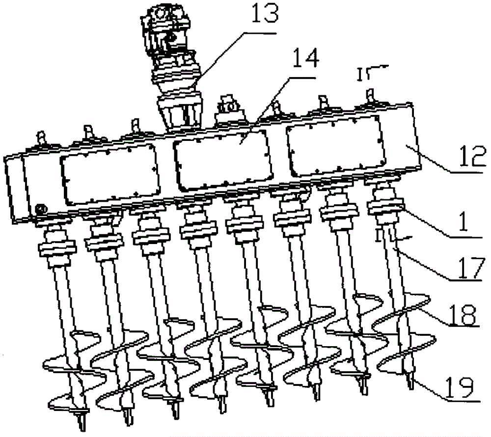
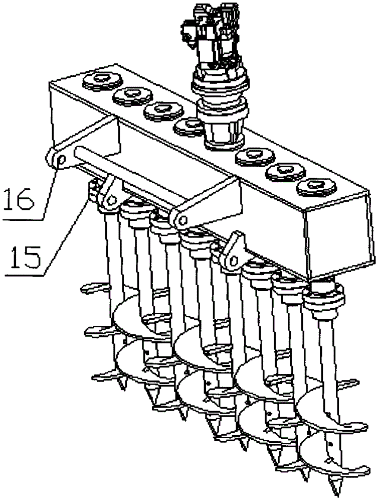
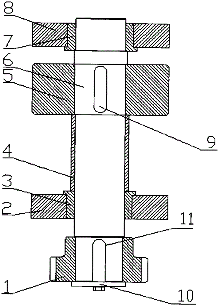
[0019] see Figure 1-3 , the present invention provides a technical solution: a mechanical transmission tillage device using sliding bearings, including a box body 12, a power shaft 13 is arranged on the top of the box body 12, and several detachable shafts are arranged on one side of the box body 12 Maintenance window 14, the other side of the box body 12 is provided with a fixed rod 16, the top of the box body 12 and its bottom are provided wi...


PUM


Abstract

The invention discloses a mechanical transmission cultivation device adopting sliding bearings. The mechanical transmission cultivation device comprises a box body, wherein a power rotating shaft is arranged at the top of the box body; a plurality of detachable maintenance windows are formed in one side of the box body; a fixing rod is arranged on the other side of the box body; a bearing pedestal is arranged at each of the top and the bottom of the box body; a second sliding bearing is mounted in the bearing pedestal at the top of the box body; a first sliding bearing is mounted in the bearing pedestal at the bottom of the box body; rotating shafts are mounted in the first sliding bearing and the second sliding bearing; the middle parts of the rotating shaft are sleeved with transmission members. According to the mechanical transmission cultivation device, a mechanical transmission manner is adopted to enable the reamer to revolve, and the first sliding bearing and the second sliding bearing are respectively arranged at two ends of the rotating shafts and grease lubrication is adopted, so that no oil leakage phenomenon occurs; and the mechanical transmission cultivation device has the advantages of greatly reducing the workload of the farmer and being cheaper than large-scale agricultural machinery in the aspect of cost and suitable for popularization.

Description

technical field [0001] The invention relates to a cultivating device, in particular to a mechanically driven cultivating device using sliding bearings, which belongs to the field of mechanical technology. Background technique [0002] Nowadays, there are still a lot of land in rural areas that need to be cultivated. Most people choose to use agricultural machinery to cultivate. Because the income in rural areas is relatively low, it is necessary to pay others to find large-scale equipment cultivators. Most people are unwilling to find large-scale cultivators. The working efficiency of the plow is clear, and the land after plowing is obviously uneven, and there will be soil clods of different sizes. At this time, it is necessary to use the traditional harrow to harrow the land, which increases the labor intensity. Moreover, traditional rakes are dangerous and can easily hurt working farmers. [0003] The working area of ​​the traditional small rotary tiller is narrow, and th...

Claims


Application Information

Patent Timeline
IPC IPC(8): A01B33/08A01B33/06
Inventor 李阳铭
Owner GUANGXI WUFENG MACHINERY CO LTD
Why Eureka
Try Eureka