Supercharge Your Innovation With Domain-Expert AI Agents!

U-shaped part orientation mechanism

A technology of orientation mechanism and parts, applied in hand-held tools, manufacturing tools, etc., can solve the problems of increasing production energy consumption, increasing the complexity of orientation mechanism, etc., and achieve the effect of fast orientation speed and simple structure

Inactive Publication Date: 2015-06-10
刘春莉
View PDF7 Cites 0 Cited by
  • Summary
  • Abstract
  • Description
  • Claims
  • Application Information

AI Technical Summary

Problems solved by technology

The disadvantage of this U-shaped part orientation mechanism in the prior art is that it needs power and a more complicated mechanism to control the movement of the upper and lower pins, which increases the complexity of the orientation mechanism and increases the energy consumption of production

Method used


Image

  • U-shaped part orientation mechanism
  • U-shaped part orientation mechanism
  • U-shaped part orientation mechanism

Examples


Embodiment Construction

[0017] The present invention will be described in detail below in conjunction with accompanying drawing:

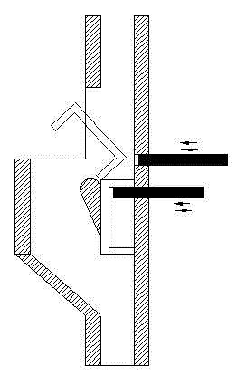
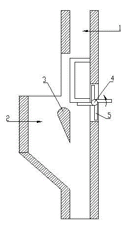
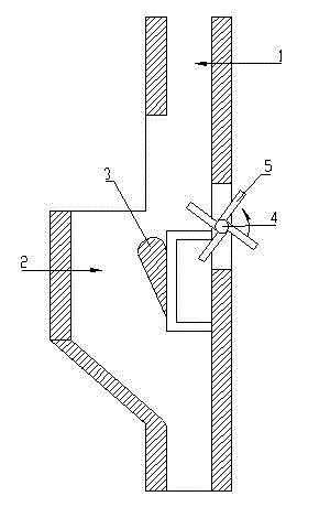
[0018] like Figures 2 to 5 As shown: the U-shaped part orientation mechanism in this embodiment includes a vertically arranged main chute 1 and an auxiliary chute 2 arranged on the main chute, and the two ends of the auxiliary chute 2 are connected to the main chute 1 In communication with each other, a cylinder 3 for turning over U-shaped parts is provided between the auxiliary chute 2 and the main chute 1, and a cylinder 3 is provided on the groove wall of the main chute 1 opposite to the cylinder 3 There is a turning wheel 4, and the circumferential surface of the turning wheel 4 is evenly provided with 4 baffle plates 5 extending radially along the turning wheel. Specifically, the length of the U-shaped part should be greater than the width of the main chute, so as to Ensure that the U-shaped part always moves along its own length in the main chute. In addition, pre...


PUM


Abstract

The invention discloses a U-shaped part orientation mechanism. The U-shaped part orientation mechanism comprises a main slide groove which is vertically arranged, and a secondary slide groove formed in the main slide groove, wherein the two ends of the secondary slide groove are communicated with the main slide groove; a column body for a U-shaped part to rotate is arranged between the secondary slide groove and the main slide groove; an overturning wheel is arranged at the position, corresponding to the column body, on the groove wall of the main slide groove; baffles which upwards extend along the radial direction of the overturning wheel are uniformly arranged on the circumference of the overturning wheel. The U-shaped part orientation mechanism has the advantages that power cannot be consumed when the U-shaped part is orientated so that the energy-saving effect is realized; the structure of the orientation mechanism is simpler than the structure of an existing orientation machine, and the orientation speed is more rapid.

Description

technical field [0001] The invention relates to a U-shaped component orientation mechanism, in particular to a U-shaped component orientation mechanism suitable for twisting pipe fittings. Background technique [0002] Orientation of parts is a relatively common problem in industrial production. Parts may come with either the open end or the closed end first, so there needs to be a mechanism that can orient all the parts so that they can be conveyed the same way. There is a mechanism for orienting U-shaped parts in the prior art, such as figure 1 , as shown, it consists of a main chute and an auxiliary chute arranged on the main chute. Two pins that reciprocate alternately in the horizontal direction are arranged on the groove wall of the groove at a position opposite to the cylinder. As the parts come down the chute, the U-shaped bottom will face right or left, all the parts that come down first hit the lower pin and stop, at this time the upper pin enters the channel, a...

Claims


Application Information

Patent Timeline
IPC IPC(8): B25B29/00
CPCB25B29/00
Inventor 张庚
Owner 刘春莉
Features
  • R&D
  • Intellectual Property
  • Life Sciences
  • Materials
  • Tech Scout
  • Unparalleled Data Quality
  • Higher Quality Content
  • 60% Fewer Hallucinations
Learn More