Charging control system of energy storage type rail transit vehicle

A charging control and rail vehicle technology, applied in the field of rail transit, can solve problems such as misoperation and strong subjectivity

Active Publication Date: 2015-06-10
ZHUZHOU ELECTRIC LOCOMOTIVE CO
View PDF8 Cites 9 Cited by
  • Summary
  • Abstract
  • Description
  • Claims
  • Application Information

AI Technical Summary

Problems solved by technology

[0003] In view of this, this application provides a charging control system for energy storage rail transit vehicles, which is used to automatically control the charging equi

Method used


Image

  • Charging control system of energy storage type rail transit vehicle
  • Charging control system of energy storage type rail transit vehicle
  • Charging control system of energy storage type rail transit vehicle

Examples


Embodiment 1

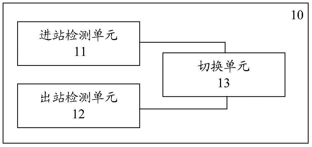
[0042] figure 1 It is a schematic diagram of a charging control system for an energy storage rail vehicle provided in an embodiment of the present application.

[0043] Such as figure 1 As shown, the charging control system provided in this embodiment includes a power supply control device 10 for controlling the power supply device to start or stop supplying power to the conductor rail of the station according to the position of the energy storage rail vehicle. The power supply control device 10 is composed of an inbound detection unit 11 , an outbound detection unit 12 and a switching unit 13 .

[0044] The station entry detection unit 11 is arranged at the station entry end of the track of the station, and is used for outputting a station entry signal when the energy storage type rail vehicle drives into the station platform, and the receiver on the vehicle is in contact with the conductor rail of the station. The incoming signal is actually a voltage signal of the contact...

Embodiment 2

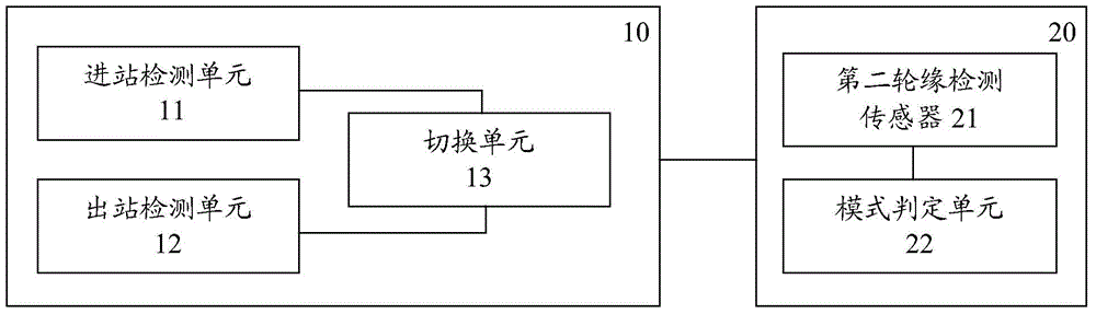
[0052] image 3 It is a schematic diagram of an energy storage rail vehicle charging control system provided by another embodiment of the present application.

[0053] Such as image 3 As shown, the charging control system provided by this embodiment is based on the previous embodiment with an additional operation mode judging device 20 .

[0054] Since the charging methods of energy storage rail vehicles are slightly different under different operating modes, it is necessary to judge its operating mode. The operation mode of the energy storage rail vehicle includes normal mode and rescue mode. In the normal mode, only the energy storage rail vehicle operates alone. In the rescue mode, it is towed by a towing vehicle or other normal energy storage rail vehicles. From the above description, the difference between normal mode and rescue mode lies in the number of wheels passing a fixed point. The general energy storage rail vehicle has 8 wheels, and the rescue vehicle has 4 w...

Embodiment 3

[0058] Figure 4 It is a schematic diagram of a charging control system for an energy storage rail vehicle provided in another embodiment of the present application.

[0059] Such as Figure 4 As shown, the charging control system provided by this embodiment is based on the previous embodiment, and a charging current control device 30 is added to control the output current of the power supply device according to the voltage rising slope during charging.

[0060] The significance of this device is that when the energy storage rail vehicle is running again, individual energy storage power supplies may be isolated by the vehicle control system due to failure. If the original current is still used to charge the energy storage rail vehicle, it may be Excessive current will cause damage to other energy storage power sources, and this charging current control device 30 is added for this reason.

[0061] The charging current control device 30 includes a current sensor 31 , a rising ...


PUM

PropertyMeasurementUnit
Lengthaaaaaaaaaa

Abstract

The invention provides a charging control system of an energy storage type rail transit vehicle. The charging control system comprises a power supply control device, wherein the power supply control device comprises an arrival detecting unit, a departure detecting unit and a switching unit; the arrival detecting unit is used for outputting an arrival signal when the energy storage type rail transit vehicle drives into a station; the departure detecting unit is used for outputting a departure signal when the energy storage type rail transit vehicle drives out of the station; the switching unit is used for controlling power supply equipment of the station to supply electric energy to conductor rails according to the arrival signal and further is used for controlling the power supply equipment to stop supplying power to the conductor rails according to the departure signal. The power supply control device of the charging control system can automatically detect arrival and departure of the energy storage type rail vehicle and controls the power supply equipment to start or stop supplying power to the conductor rails according to a detecting result through the switching unit, so that the control device can replace an operation worker to operate the power supply equipment, and the problem of false operation easily caused by higher subjectivity of a manual operation mode can be solved.

Description

technical field [0001] The present application relates to the technical field of rail transit, and more specifically, relates to a charging control system of an energy storage type rail transit vehicle. Background technique [0002] The charging feature of the energy storage rail transit vehicle is high-current fast charging. When the energy storage rail transit vehicle enters the platform, it uses high-current fast charging to deliver a large amount of electric energy to the energy storage device in a short time. The current charging procedure is that when the energy storage vehicle enters the platform, the platform personnel notify the charging operator through the sound and light signal. After receiving the sound and light signal, the charging operator controls and connects the power supply equipment to output electric energy to the conductive rail and connects to the conductive rail. The power receiving device of the energy storage rail transit vehicle starts to receive ...

Claims


Application Information

Patent Timeline
IPC IPC(8): B60M3/00
Inventor 陈盛才张彦林张伟先胡润文刘洋柯建明陈朝辉李玉梅文午付亚娥王雪莲汪俊黄钰强沈朝喜董凯文
Owner ZHUZHOU ELECTRIC LOCOMOTIVE CO
Why Eureka
Try Eureka