
Dumper tail structure with hydraulic locking device

A locking device and dump truck technology, which is applied to the upper structure of the truck, the upper structure, and the vehicle with inclined load movement, etc., which can solve the problem of loose locking, large gap between the rear door and the box body, and poor sealing of the rear door, etc. problems, to ensure safety and reliability, good locking effect, and prevent material leakage

Active Publication Date: 2015-06-10
SINO TRUK JINAN POWER
View PDF7 Cites 12 Cited by
  • Summary
  • Abstract
  • Description
  • Claims
  • Application Information

AI Technical Summary

Problems solved by technology

[0002] During the transportation of the dump truck, if the back door is not tightly sealed and locked firmly, material leakage is prone to occur
At present, most of the locking devices of dump trucks are in the form of mechanical locking. The mechanical locking depends on the movement process of the lifting of the cargo box to realize automatic control. When the cargo box is not lifted, the locking device cannot operate.
In addition, after long-term use of the mechanical locking device, due to the existence of factors such as mechanical wear and permanent deformation, the gap between the back door and the box body will become larger and larger, and the back door will not be able to prevent material leakage, and the locking device will not work. Some functions are equivalent to failure

Method used


Image

  • Dumper tail structure with hydraulic locking device
  • Dumper tail structure with hydraulic locking device
  • Dumper tail structure with hydraulic locking device

Examples


Embodiment Construction

[0022] The present invention will be further described below in conjunction with the accompanying drawings and embodiments.

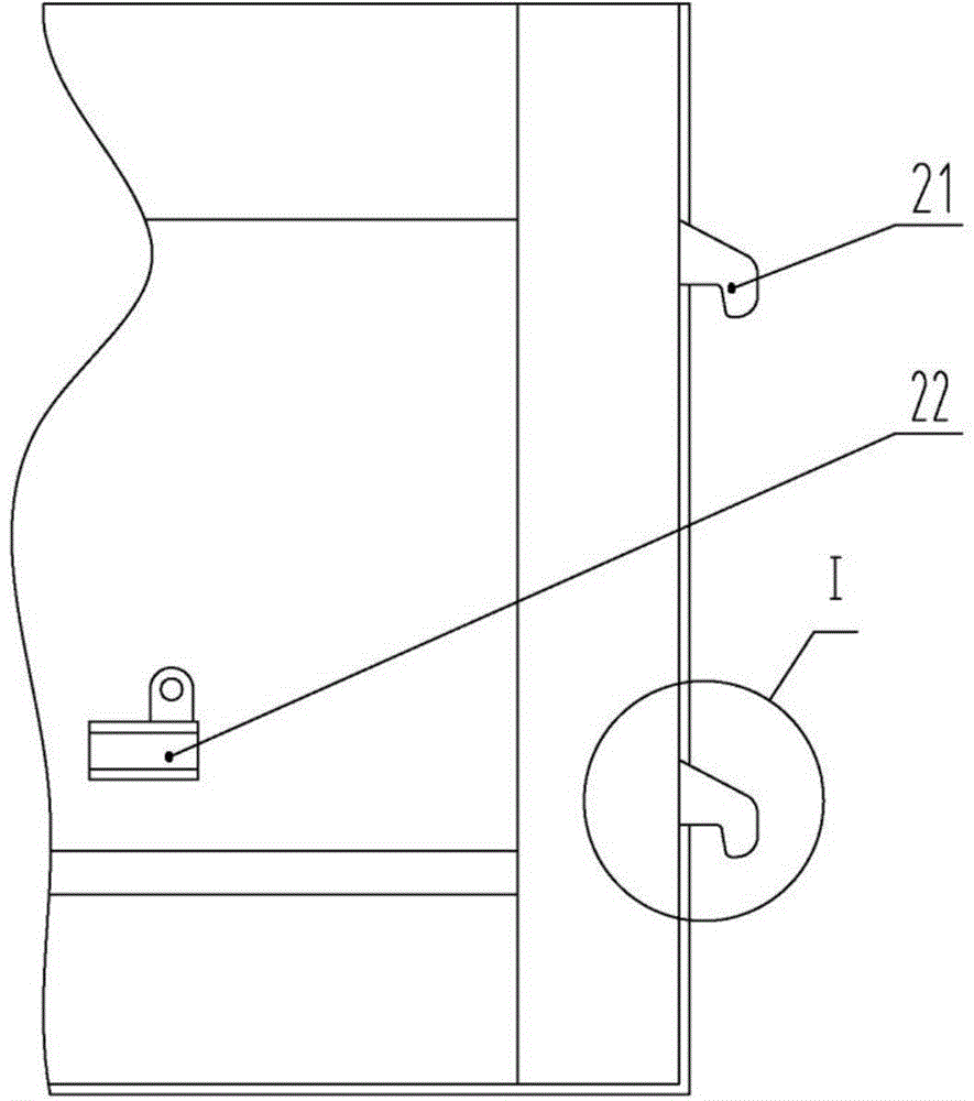
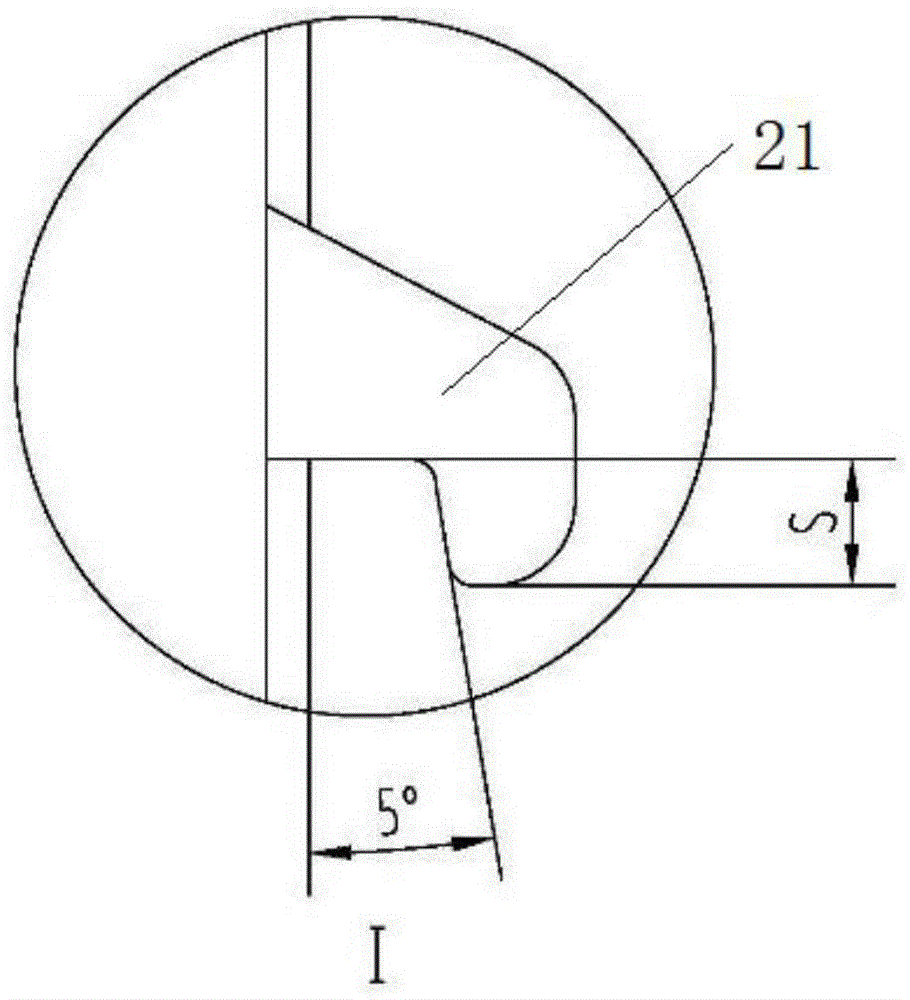
[0023] Such as figure 1 Shown, the dump truck casing, the casing 2 rear end is welded with hook 21, and the oil cylinder seat 22 and bearing pin 6 are welded at the appropriate place of side bottom.

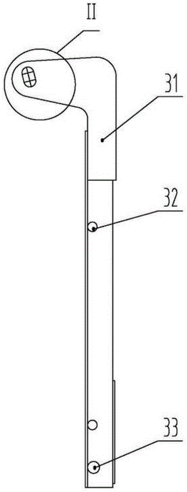
[0024] Such as image 3 Shown, rear door body, rear door 3 tops are welded with hinged plate 31, and both sides are welded with hook clamping shaft 32 and lock hook clamping shaft 33; There are oblong holes on the hinged plate, which can move up and down relative to the dump truck casing. Wherein there are two hook clamping shafts 32 on each side, and the hook clamping shafts 32 are matched with the hooks 21 fixed on the casing 2 .

[0025] Such as Figure 5 As shown, the front end of the double-acting hydraulic cylinder 4 is hinged on the cylinder seat 22 of the box body 2 through the hinge shaft 41, and the rear end is hinged on the upper part of the ...


PUM


Abstract

The invention discloses a dumper tail structure with a hydraulic locking device. The upper part of a back door body is a hinge plate which is hinged with a hinge seat, the hinge seat is arranged at the upper end of a dumper box body, an oblong hole is formed in a connection part between the hinge plate and the hinge seat and is matched with a connecting shaft on the hinge seat, and the connecting shaft and the oblong hole can generate relative movement; a latch hook clamping shaft is arranged at the lower part of the back door body, and a hook clamping shaft is arranged between the hinge plate and the latch hook clamping shaft on the back door body and is clamped with a hook on the side wall of the dumper box body. According to the dumper tail structure with the hydraulic locking device, a back door and the hydraulic locking device use cooperatively, the locking effect is excellent, the fitting degree of the back door and the box body can be improved, and material leakage can be effectively prevented; the hydraulic locking device can further prevent the back door from jumping up, and ensure the safety and the reliability of a vehicle during using; the hydraulic locking device can further increase the pushing force of a hydraulic cylinder, and provides a larger locking force; the dumper tail structure with the hydraulic locking device has the advantages of being simple in operation, safe, reliable and high in controllability.

Description

technical field [0001] The invention belongs to the technical field of dump trucks, in particular to a tail structure of a dump truck with a hydraulic locking device. Background technique [0002] During the transportation of the dump truck, if the back door is not tightly sealed and locked firmly, material leakage is prone to occur. At present, most of the locking devices of dump trucks are in the form of mechanical locking. The mechanical locking depends on the automatic control of the lifting movement of the cargo box. When the cargo box is not lifted, the locking device cannot operate. In addition, after long-term use of the mechanical locking device, due to the existence of factors such as mechanical wear and permanent deformation, the gap between the back door and the box body will become larger and larger, and the back door will not be able to prevent material leakage, and the locking device will not work. Some functions are equivalent to failure. Contents of the i...

Claims


Application Information

Patent Timeline
Patent Type & Authority Applications(China)
IPC IPC(8): B60P1/26B62D33/037
Inventor 梁尔松李喜艳赵娜刘守科董彦来吴瑞宪
Owner SINO TRUK JINAN POWER
Learn More