Deformation device of crawler belt running system

A deformation device and crawler technology, applied to tracked vehicles, transportation and packaging, motor vehicles, etc., can solve the problems of tracked vehicles such as reduced ground area, easy slipping, sinking, and good cross-ditch performance, and achieve driving ability and anti-sinking Effects of ability enhancement, overcoming driving ability and passability, and expanding application range

Inactive Publication Date: 2015-06-10
CHANGSHA XINGJU AGRI MACHINERY
View PDF5 Cites 8 Cited by
  • Summary
  • Abstract
  • Description
  • Claims
  • Application Information

AI Technical Summary

Problems solved by technology

[0002] Paddy fields in the south are often planted with rice, and the paddy fields are kept in a humid state for a long time, so the soil is soft and the mud feet are deep, and the operating machinery is easy to slip and sink when working in the field; currently, the tracked vehicles are driven by crawlers, and the grounding area is large, and the grounding specific pressure is small. It has good ditch-crossing performance and is less destructive to farmland and roads, so it is widely used in the driving system of rice field operations in the south. However, the track-type driving mechanism has poor passability and ridge-crossing ability due to the small diameter of the driving wheel and support wheel. If the passability or ridge-crossing ability of the tracked vehicle is to be improved, the diameter of the driving wheel and the supporting wheel needs to be increased, and the increase in the diameter of the driving wheel and the supporting wheel will reduce the ground contact area of ​​the tracked vehicle and reduce the driving capacity of the track.

Method used


Image

  • Deformation device of crawler belt running system
  • Deformation device of crawler belt running system
  • Deformation device of crawler belt running system

Examples


Embodiment Construction

[0024] In order to make the technical means, creative features, goals and effects achieved by the present invention easy to understand, the present invention will be further described below in conjunction with specific illustrations.

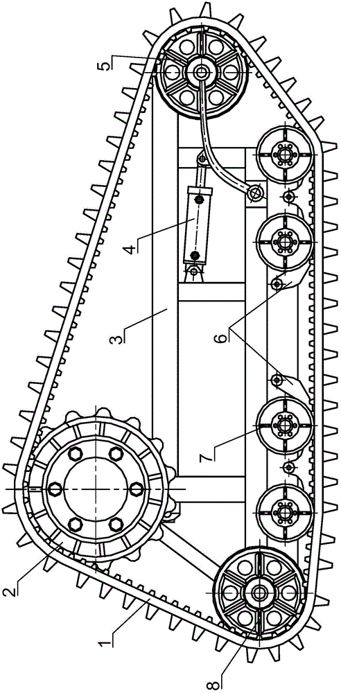
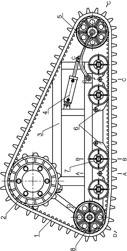
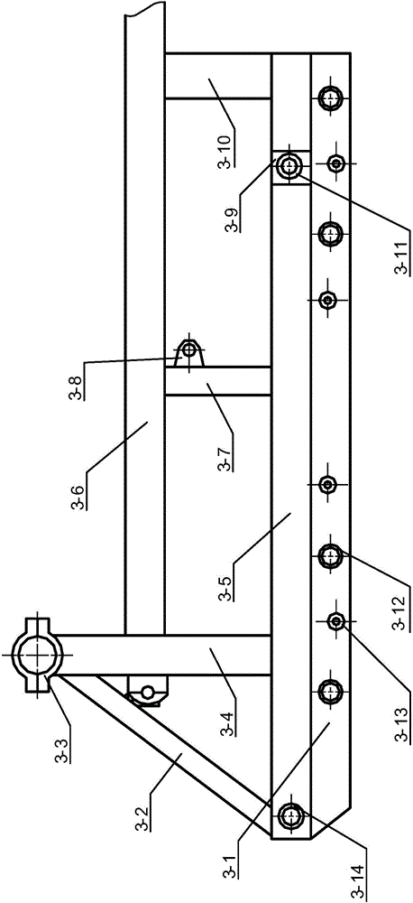
[0025] see Figure 1 to Figure 9 A deformation device for a crawler driving system, comprising a crawler 1, a drive wheel 2, a vehicle frame 3, a hydraulic cylinder 4, a front support wheel 5, an inner guide plate 6, a load-bearing wheel 7, a rear support wheel 8, a crawler main body 1-1, Drive groove 1-2, limit tooth 1-3, drive tooth 1-4, bottom frame 3-1, inclined connecting rod 3-2, driving wheel bushing 3-3, rear connecting rod 3-4, bottom frame reinforcement frame 3-5, upper frame 3-6, middle connecting rod 3-7, hydraulic cylinder connecting seat 3-8, front supporting wheel connecting pin 3-9, front connecting rod 3-10, front supporting wheel connecting pin bracket 3- 11. Bearing wheel support pin 3-12, inner guide plate support pin 3-13, ...


PUM


Abstract

A deformation device of a crawler belt running system comprises a crawler belt, a driving wheel, a frame, a hydraulic cylinder, a front support wheel, inner guide plates, bearing wheels and a rear support wheel. The driving wheel is mounted above one end of an upper frame, the front support wheel is mounted below the other end of the upper frame, the front support wheel is connected with the hydraulic cylinder mounted on the frame, and the rear support wheel and the bearing wheels are mounted on an underframe. In addition, the driving wheel, the front support wheel and the rear support wheel are wrapped in the crawler belt, the inner guide plates are welded on the underframe and contact with the inner surface layer of the crawler belt. By extending and retracting the hydraulic cylinder to change the up and down positions of the front support wheel and the rear support wheel, shape of the deformation device is changed, so that the grounding area of the crawler belt is enlarged when a crawler belt vehicle is driven to run, and driving ability and trapping prevention ability are improved; when the crawler belt vehicle overpasses ridges, the approach angle of the crawler belt is increased, passability of the crawler belt vehicle is effectively improved and application range of the crawler belt vehicle is broadened.

Description

technical field [0001] The invention relates to the technical field of crawler belt travel, in particular to a deformation device for a crawler belt travel system. Background technique [0002] Paddy fields in the south are often planted with rice, and the paddy fields are kept in a humid state for a long time, so the soil is soft and the mud feet are deep, and the operating machinery is easy to slip and sink when working in the field; currently, the tracked vehicles are driven by crawlers, and the grounding area is large, and the grounding specific pressure is small. It has good ditch-crossing performance and is less destructive to farmland and roads, so it is widely used in the driving system of rice field operations in the south. However, the track-type driving mechanism has poor passability and ridge-crossing ability due to the small diameter of the driving wheel and support wheel. If the passability or ridge-crossing ability of the tracked vehicle is to be improved, the...

Claims


Application Information

Patent Timeline
IPC IPC(8): B62D55/08B62D55/10B62D55/14
Inventor 孙超然周志周峰
Owner CHANGSHA XINGJU AGRI MACHINERY
Why Eureka
Try Eureka