Single-shot laser pulse detection device
A detection device, laser pulse technology, applied in the direction of instruments, etc., can solve the problem that the measurement method does not have a ready-made standard, etc., and achieve the effect of improving the dynamic range
- Summary
- Abstract
- Description
- Claims
- Application Information
AI Technical Summary
Problems solved by technology
Method used
Image

Examples
Embodiment 1
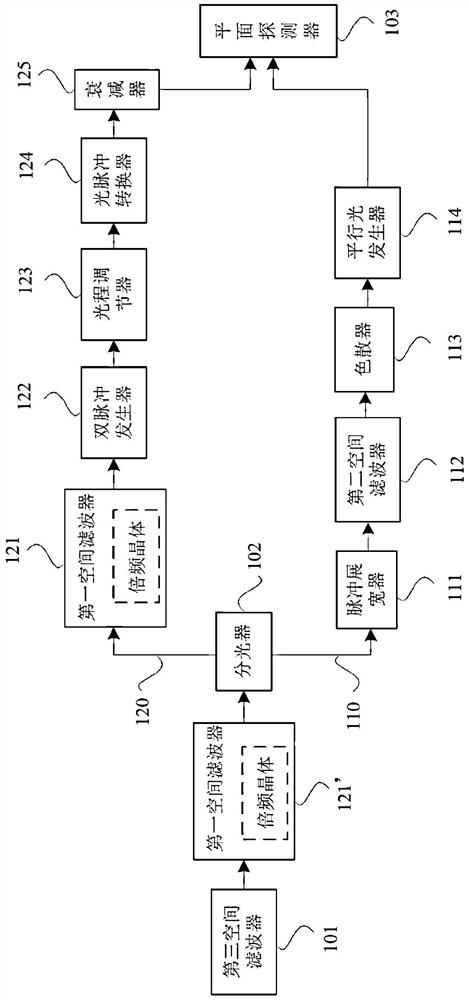
[0081] like figure 2 As shown, the computer 100 controls the trigger 85 to trigger the pulse generator (not shown in the figure) to generate a single laser pulse to be measured, and then the computer 100 controls the opening time of the electric shutter 1. When the laser pulse to be measured passes through the electric shutter At 1 (Shutter), the single-shot laser pulse detection device and the pulse generation device run synchronously to reduce the stray light in the instrument and improve the signal-to-noise ratio of the instrument itself. Then, the polarization of the laser pulse to be measured is deflected by 45 degrees through the half-wave plate 2 to adjust the splitting ratio; Filter), the soft edge diaphragm ceramic aperture 71 is arranged at its focal point, is to make the laser pulse to be measured become a super-Gaussian flat-top beam, and at the same time expand the beam aperture M1 times; Two paths: the reference light path for p-polarization in the upper arm an...
Embodiment 2
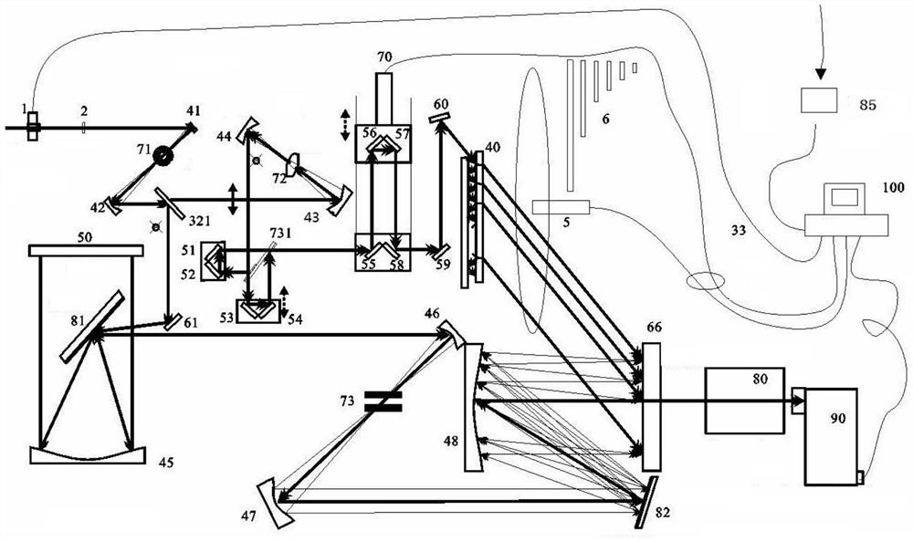
[0087] like image 3 As shown, the computer 100 controls the trigger 85 to trigger the pulse generator (not shown in the figure) to generate a single laser pulse to be measured, and then the computer 100 controls the opening time of the electric shutter 1. When the laser pulse to be measured passes through the electric shutter At 1:00, the single-shot laser pulse detection device and the pulse generation device run synchronously, reducing the stray light in the instrument and improving the signal-to-noise ratio of the instrument itself. Then, the laser pulse to be measured is polarized and deflected by the half-wave plate 2 to meet the phase matching needs of the nonlinear crystal (ooe) to adjust the splitting ratio; The input pulse is divided into two paths by the proportional beam splitter 321: the upper arm p-polarized frequency-doubling reference light path and the lower arm s-polarized fundamental frequency detection light path.
[0088] The reference optical path of the...
Embodiment 3
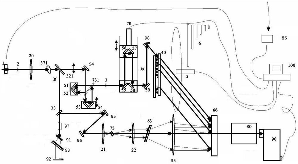
[0092] like Figure 4 As shown, the computer 100 controls the trigger 85 to trigger the pulse generator (not shown in the figure) to generate a single laser pulse to be measured, and then the computer 100 controls the opening time of the electric shutter 1. When the laser pulse to be measured passes through the electric shutter At 1:00, the single-shot laser pulse detection device and the pulse generation device run synchronously, reducing the stray light in the instrument and improving the signal-to-noise ratio of the instrument itself. Then, the laser pulse to be measured is polarized and deflected by the half-wave plate 2 to meet the phase matching needs of the nonlinear crystal (ooe) to adjust the splitting ratio; The input pulse is divided into two paths by the proportional beam splitter 321: the upper arm p-polarized frequency-doubling reference light path and the lower arm s-polarized fundamental frequency detection light path.
[0093] Wherein, the reference optical p...
PUM
 Abstract
Description
Claims
Application Information
 - R&D
- Intellectual Property
- Life Sciences
- Materials
- Tech Scout
- Unparalleled Data Quality
- Higher Quality Content
- 60% Fewer Hallucinations
Browse by: Latest US Patents, China's latest patents, Technical Efficacy Thesaurus, Application Domain, Technology Topic, Popular Technical Reports.
© 2025 PatSnap. All rights reserved.Legal|Privacy policy|Modern Slavery Act Transparency Statement|Sitemap|About US| Contact US: help@patsnap.com