
Anti-rollover structure of automobile power battery pack

A technology for automotive power batteries and power battery packs, which is applied to structural parts, battery pack components, circuits, etc., can solve the problems of battery packs turning forward and insufficient space utilization, and achieve the effect of preventing forward turning and reasonable use of space

Active Publication Date: 2016-12-07
ZHEJIANG GEELY AUTOMOBILE RES INST CO LTD +1
View PDF5 Cites 0 Cited by
  • Summary
  • Abstract
  • Description
  • Claims
  • Application Information

AI Technical Summary

Problems solved by technology

[0004] The present invention provides an automobile power battery pack anti-turnover structure that fully utilizes the interior space of the car and can prevent the battery pack from turning forward during a collision, and solves the problem that the battery pack is fixed on the rear seat only by connecting the bottom to the vehicle body The space in the rear is not fully utilized, and the battery pack is prone to flipping forward during a collision

Method used


Image

  • Anti-rollover structure of automobile power battery pack
  • Anti-rollover structure of automobile power battery pack
  • Anti-rollover structure of automobile power battery pack

Examples


Embodiment 1

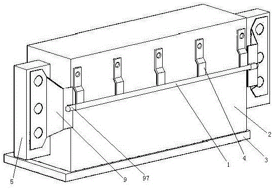
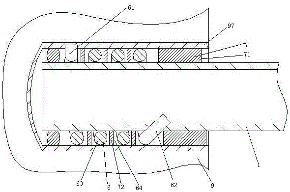
[0024] Embodiment one, see figure 1 , an automobile power battery pack anti-turnover structure, comprising a protective bar 1. The protection rod 1 is a tubular structure, specifically a steel pipe. The protective bar 1 extends in the width direction of the vehicle. The protective bar 1 is located behind the rear seats of the car. The protective bar 1 is located in front of the power battery pack 2 . The power battery pack 2 is located in front of the trunk. The power battery pack 2 rests on the floor 3 of the vehicle. The protection bar 1 is connected with five battery pack fixing brackets 4 . The five battery pack fixing brackets 4 are distributed along the length direction of the protection bar 1 , that is, the width direction of the vehicle. The battery pack fixing bracket 4 is a block structure. The battery pack fixing bracket 4 is welded together with the protection bar 1. The battery pack fixing bracket 4 is located above the protection bar 1 . The battery pack ...

Embodiment 2

[0026] Embodiment two, the difference with embodiment one is:

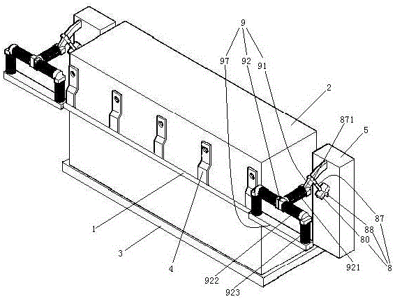
[0027] see image 3 , the connecting frame 9 is connected with a coating heating mechanism 8 . The connecting frame 9 also includes a connecting rod 91 and five damping rods 92 . The connecting rod 91 is an arc-shaped structure that arches upwards (of course, downwards is also possible). The five damping rods 92 are a longitudinal damping rod 921 , two horizontal damping rods 922 and two vertical damping rods 923 . One end of the connecting rod 91 is connected with the body 5 of the automobile. The other end of the connecting rod 91 is connected with one end of the longitudinal damping rod 921 . One end of the two transverse shock absorbing rods 922 is connected with the other end of the longitudinal shock absorbing rod 921. The upper ends of the two vertical shock absorbing rods 923 are respectively connected with the other ends of the two transverse shock absorbing rods 922 . The lower ends of the two vert...


PUM


Abstract

The invention relates to the technical field of automobile manufacturing. An automobile power battery pack anti-turnover structure, including a protective bar, the power battery pack is installed behind the rear seat of the car, the power battery pack is located in front of the trunk of the car, the protective bar is located in front of the power battery pack, and the protective bar is Tubular structure, the protective bar extends along the width direction of the car, and the protective bar is equipped with a number of battery pack fixing brackets distributed along the length direction of the protective bar. The battery pack fixing bracket is connected with the power battery pack, and both ends of the protective bar are connected. frame, and the connecting frame is connected with the body of the car. The present invention provides an automobile power battery pack anti-turnover structure that fully utilizes the interior space of the car and can prevent the battery pack from turning forward during a collision, and solves the problem that the battery pack is fixed on the rear seat only by connecting the bottom to the vehicle body The space at the rear is insufficiently utilized, and the battery pack is prone to flipping forward during a collision.

Description

technical field [0001] The invention relates to the technical field of automobile manufacturing, in particular to an automobile power battery pack anti-turnover structure. Background technique [0002] An electric or hybrid vehicle is provided with a battery pack for driving the motor, and the battery pack for driving the motor is a power battery pack. The power battery pack is installed in the body of the car through the battery pack installation structure. A power battery pack installation structure is disclosed in a patent document with the Chinese patent number 201220611004X, the authorized publication date being May 29, 2013, and the title "An Installation Structure for an Integrated Battery Pack". Some battery packs are installed in the engine room of the car, and some are suspended at the bottom of the passenger compartment, but the above installation locations all have insufficient utilization of the interior space of the car body. For this reason, a battery pack i...

Claims


Application Information

Patent Timeline
Patent Type & Authority Patents(China)
IPC IPC(8): H01M2/10H01M50/242H01M50/244H01M50/249H01M50/258
CPCH01M50/20Y02E60/10
Inventor 王铁丰朱启维石振吕荣清吴成明冯擎峰
Owner ZHEJIANG GEELY AUTOMOBILE RES INST CO LTD
Learn More