Air duct cooling system for vehicle battery pack

A vehicle-mounted battery pack and cooling system technology, which is applied in the field of vehicle-mounted battery pack air duct cooling system, can solve problems such as the failure of the battery pack cooling device, and achieve the effect of improving the heat dissipation effect

Active Publication Date: 2017-03-08
ZHEJIANG GEELY AUTOMOBILE RES INST CO LTD +1
View PDF1 Cites 0 Cited by
  • Summary
  • Abstract
  • Description
  • Claims
  • Application Information

AI Technical Summary

Problems solved by technology

[0006] Another purpose of the present invention on the basis of the first purpose is to overcome the problem that the cooling device of the vehicle power battery pack in the prior art relies on a fan to dissipate heat. Once the fan fails, the cooling device of the battery pack will fail; to provide a During the driving of the car, even if the fan of the battery pack cooling device fails, the on-board battery pack air duct cooling system can still dissipate heat from the battery pack

Method used


Image

  • Air duct cooling system for vehicle battery pack
  • Air duct cooling system for vehicle battery pack

Examples


Embodiment 1

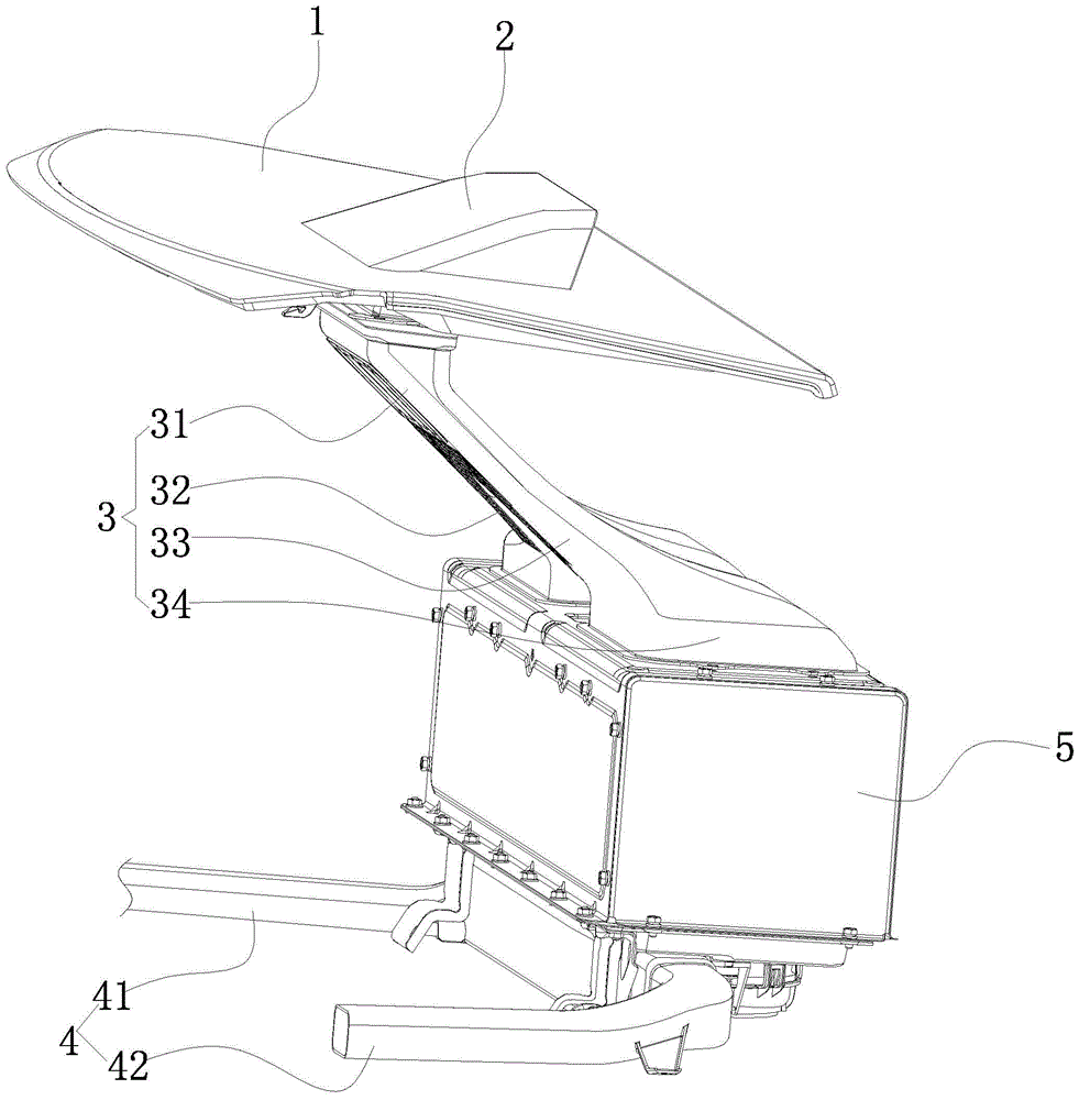
[0025] Embodiment 1: as figure 1 As shown, a vehicle-mounted battery pack air duct cooling system includes a battery pack case 5 , an air intake duct 3 and an exhaust duct 4 . The trunk partition 1 is provided with an air inlet (the trunk partition refers to the trunk partition between the rear windshield of the car and the adjacent rear seats). A wind guide cover 2 with an opening facing the front of the car is arranged on the trunk partition of the car and is located directly above the air inlet. An upper vent is provided on the top surface of the battery pack housing. The upper vent consists of left and right upper vents. A lower vent is provided on the bottom surface of the battery pack shell. The lower vent consists of left and right lower vents.

[0026] The air intake duct is located under the trunk partition of the car. The air inlet duct is Y-shaped, and it is composed of a main air inlet pipe 31 and left and right branch air inlet pipes 32, 33 communicated with ...

Embodiment 2

[0029] Embodiment 2: the remaining structure of this embodiment is with reference to embodiment 1, and its difference is:

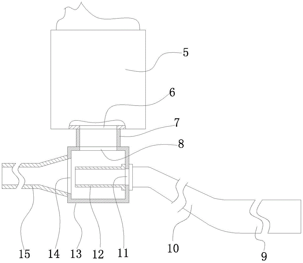
[0030] Such as figure 2 As shown, a vehicle-mounted battery pack air duct cooling system also includes a guide duct 9 , an air outlet duct 15 and a negative pressure suction container 13 . An air outlet 6 is also provided on the bottom surface of the battery pack casing. The air exhaust port communicates with the inner cavity of the battery pack housing. The negative pressure suction container is located below the battery pack housing, and a ventilation hole 8 is arranged on the top surface of the negative pressure suction container. An air inlet 11 and an exhaust hole 14 are also provided on the side of the negative pressure suction container, and the air inlet and the exhaust hole are located on opposite side surfaces of the suction container. The suction container is provided with an air jet pipe 12 extending from the air intake hole to the exhaust h...


PUM


Abstract

The invention discloses an air channel cooling system of a vehicle-mounted battery pack and aims to provide an air channel cooling system of a vehicle-mounted battery pack, which is capable of effectively dissipating heat of batteries in the vehicle-mounted battery pack, discharging the air in a passenger compartment out of a vehicle body and continuously retaining fresh air of the passenger compartment. The air channel cooling system of the vehicle-mounted battery pack comprises a battery pack housing, an air inlet pipeline and an air outlet pipeline, wherein an upper air vent is formed in the top surface of the battery pack housing; a lower air vent is formed in the bottom surface of the battery pack housing; one end of the air inlet pipeline is connected to the upper air vent in a sealing manner; the other end of the air inlet pipeline is communicated with the vehicle passenger compartment; one end of the air outlet pipeline is connected with the lower air vent in a sealing manner; the other end of the air outlet pipeline is communicated with an external space of the vehicle body; an air exhaust fan is arranged between the air outlet pipeline and the lower air vent or is arranged on the air outlet pipeline.

Description

technical field [0001] The invention relates to the field of heat dissipation of automobile batteries, in particular to an air duct cooling system for a vehicle battery pack. Background technique [0002] As the main energy storage component of new energy vehicles or hybrid vehicles, the battery pack is a key component of new energy vehicles or hybrid vehicles, and its performance and service life have an important impact on the performance of the vehicle. The battery pack in the on-board battery pack is composed of multiple battery cells in series, and the loading space on the vehicle is limited, the number of batteries required by the vehicle is large, and the batteries are closely arranged and connected; when the battery pack is working, it will generate A certain amount of heat, if the battery pack cannot get good heat dissipation and cooling, and it is in a high temperature environment for a long time, it will seriously affect the performance and life of the battery. ...

Claims


Application Information

Patent Timeline
Patent Type & Authority Patents(China)
IPC IPC(8): H01M10/6563H01M10/6556H01M10/6554
CPCY02E60/10
Inventor 杨振鹏曾国家禹洋李福彬朱启维汤小生谢世滨吴成明冯擎峰
Owner ZHEJIANG GEELY AUTOMOBILE RES INST CO LTD
Why Eureka
Try Eureka