Control device and shift-by-wire system having the same

A technology of control equipment and current detection circuit, which is applied in the direction of control system, general control system, control/regulation system, etc., can solve the problems of not being able to learn the standard position correctly, and achieve the effect of avoiding the learning operation of the standard position and improving the learning accuracy

Active Publication Date: 2018-06-12
DENSO CORP
View PDF6 Cites 0 Cited by
  • Summary
  • Abstract
  • Description
  • Claims
  • Application Information

AI Technical Summary

Problems solved by technology

However, when the system includes a physical circuit for detecting the sum of the currents flowing through the phases of the windings of the motor and a physical circuit for limiting the current flowing through the windings, if the circuit is damaged, the standard position may not be correctly learned

Method used


Image

  • Control device and shift-by-wire system having the same
  • Control device and shift-by-wire system having the same
  • Control device and shift-by-wire system having the same

Examples


no. 2 example

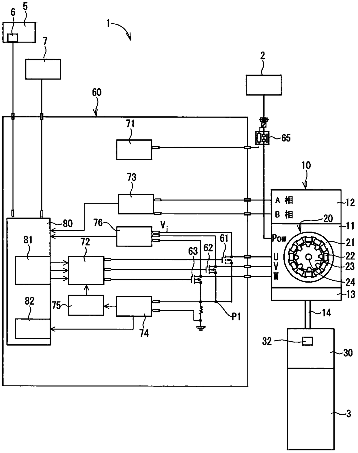
[0105] A control device and a shift-by-wire system having the same according to another example embodiment are shown in Figure 5 middle.

[0106] Specifically, the ECU 60 includes a relay 65, MOS transistors 61-63, a relay drive circuit 71, a MOS drive circuit 72, an encoder detection circuit 73, a current detection circuit 74, a current limiting circuit 75, a voltage detection circuit 76, a constant current circuit 77 and MPU 80.

[0107] The constant current circuit 77 is connected to the junction P1. The constant current circuit 77 causes a current corresponding to a predetermined constant current (ie, Iconst) to flow at the junction P1.

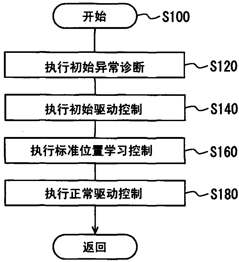
[0108] The MPU 80 includes an abnormality detection device 82 as a functional device. Next, refer to Figure 6 Processing related to abnormality detection by the current detection circuit 74 performed by the abnormality detection means 82 in the MPU 80 is explained.

[0109] When the initial abnormality diagnosis is performed, proce...


PUM


Abstract

The invention discloses a control device and a shift-by-wire system having the same, wherein the control device controls a motor (20) to drive an object (32), and includes: a relay (65) enabling and interrupting power supply to the motor ; Switching devices (61‑63) for multiple phases for enabling and interrupting the excitation of windings (22); controllers (72, 80, 81) for relays and switching devices; current detection circuits (74) for The current flowing through the confluence of the winding and the switching device; the current limiting circuit (75), used to maintain the average value of the current within a predetermined range; the standard position learning device (80), used to learn the standard position of the motor; the voltage detection circuit (76) for detecting voltage applied to each switching device; and abnormality detecting means (80, 82) for detecting current based on voltage and current when the relay is turned on and the switching devices are all turned off Detect anomalies in circuits.

Description

technical field [0001] The present disclosure relates to a control device for controlling the operation of an electric motor and a shift-by-wire system having the same. Background technique [0002] Conventionally, in vehicle control technology, a drive-by-wire system is known that uses a drive-by-wire circuit to electrically control an actuator that changes a state of a vehicle according to an instruction from a driver of the vehicle. For example, Patent Document 1 teaches a shift-by-wire system that switches a shift lever according to a driver's instruction. In this system, the operation of an actuator having a brushless motor is controlled to change a shift position by rotatably driving a brake plate in a shift position switching device. [0003] In the shift-by-wire system according to Patent Document 1, based on the count value of the pulse signal from the encoder for outputting the pulse signal every predetermined angle in synchronization with the rotation of the moto...

Claims


Application Information

Patent Timeline
Patent Type & Authority Patents(China)
IPC IPC(8): H02P25/00H02H7/08
CPCH02P29/0241G06N20/00G05B13/0265H02P25/00
Inventor 吉田和弘山田纯
Owner DENSO CORP
Why Eureka
Try Eureka