
A built-in intelligent pdu system cabinet

An intelligent, cabinet-based technology, applied in the direction of casing/cabinet/drawer parts, rack/frame structure, etc., can solve problems such as waste, welding trouble, and lack of real-time abnormal alarm function, etc., to achieve good results and general use strong effect

Active Publication Date: 2018-08-14
宁波腾浪网络通信设备有限公司
View PDF13 Cites 0 Cited by
  • Summary
  • Abstract
  • Description
  • Claims
  • Application Information

AI Technical Summary

Problems solved by technology

[0002] The existing intelligent PDU is installed in its matching control cabinet. The existing control cabinet is connected by welding, which is troublesome to weld, and the mechanism inside the cabinet cannot be adjusted. Some electronic modules and control board hosts installed in it Component installation needs to match the internal space of the control cabinet. When the control cabinet is too small, it cannot be installed. It is necessary to purchase a control cabinet with a larger space. This is very troublesome, and it will cause waste and increase costs.
[0003] At the same time, the existing control cabinets generally use ordinary door locks, and there are no display screens and other components to constantly reflect various internal conditions, such as temperature, operating status, etc.
[0004] Moreover, smart PDUs currently on the market generally intelligently provide local measurement and display of current and voltage, and some smart PDUs with remote communication functions also intelligently realize one-to-one remote communication functions, and do not have real-time abnormal alarm functions.

Method used


Image

  • A built-in intelligent pdu system cabinet
  • A built-in intelligent pdu system cabinet
  • A built-in intelligent pdu system cabinet

Examples


Embodiment Construction

[0031] The present invention will be described in detail below in conjunction with accompanying drawings and specific preferred embodiments, so that the advantages and features of the present invention can be more easily understood by those skilled in the art. range is limited.

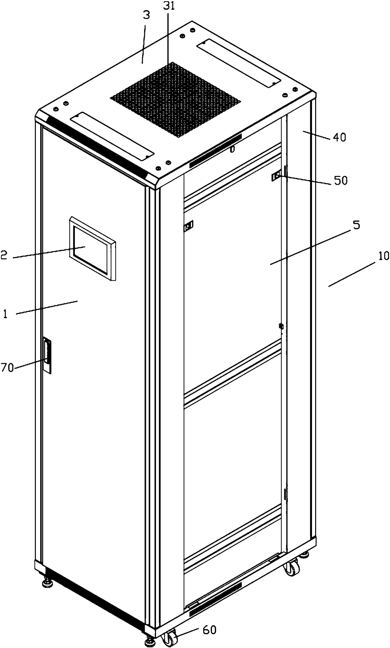
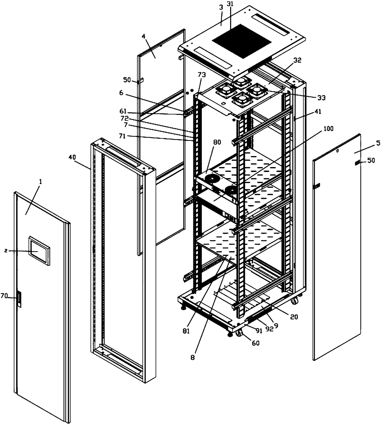
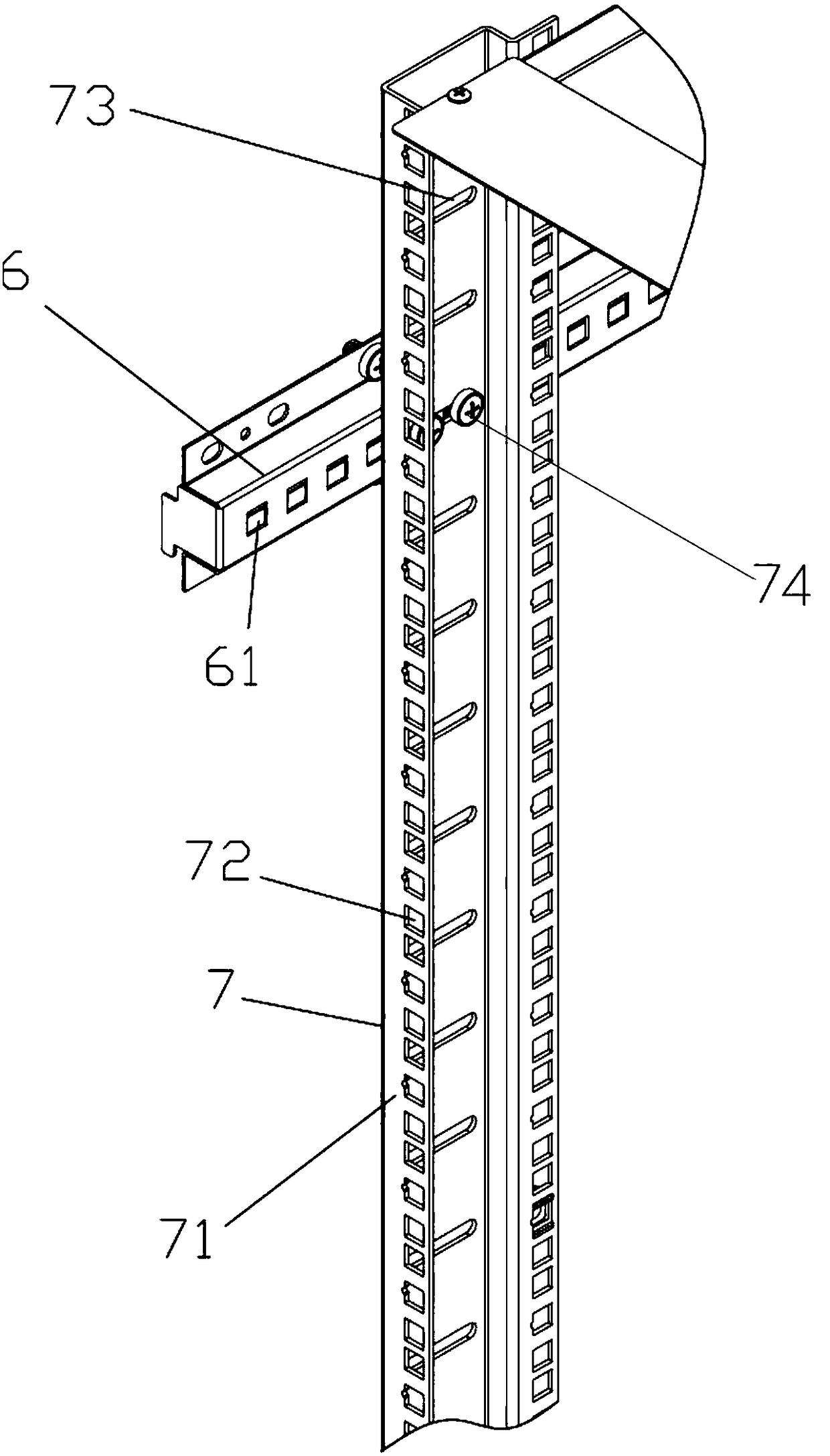
[0032] Examples, see e.g. Figures 1 to 5 As shown, a cabinet for an intelligent PDU system includes a cabinet body 10, an LCD touch screen 2 is fixed on the cabinet door 1 of the cabinet body 10, a mesh through hole 31 is provided on the top board 3 of the cabinet body 10, and the back side of the top board 3 A connection plate 32 is fixed, and a plurality of fans 33 are fixed on the connection plate 32. The outlet ends of the fans 33 are vertically facing the mesh through-hole 31, and the inlet ends of the fans 33 are vertically downward. The left side of the cabinet body 10 A plurality of horizontal adjustment beams 6 are fixed on the inner side of the plate 4 and the right side plate 5, and a plu...


PUM


Abstract

The invention discloses a built-in intelligent PDU (power distribution unit) system cabinet which comprises a cabinet body and an intelligent PDU, an LCD (liquid crystal display) touch screen is fixed on a cabinet door of the cabinet body, a connecting plate is fixed at the back of a top plate of the cabinet body, a plurality of fans are fixed on the connecting plate, a plurality of transverse adjusting beams are fixed on the inner side faces of a left side plate and a right side plate of the cabinet body, at least two vertical beams are fixed on the transverse adjusting beams fixed on left side plate or the right side plate, a plurality of middle supporting plates are fixed on at least four vertical beams through bolts, a temperature control unit is fixed in the front of one middle supporting plate, the intelligent PDU is fixed in the front of one middle supporting plate and comprises a shell, a main control board, a power board, a branch control board and a WEB server are arranged in the shell, the transverse adjusting beams and the vertical beams are arranged inside the cabinet body, the size of an internal support is adjusted, so that an internal particular use space of the cabinet body can be adjusted, and the built-in intelligent PDU system cabinet can monitor temperature, current, humidity and the like in real time.

Description

Technical field: [0001] The invention relates to the technical field of electric control cabinet equipment, and more specifically relates to a cabinet with a built-in intelligent PDU system. Background technique: [0002] The existing intelligent PDU is installed in its matching control cabinet. The existing control cabinet is connected by welding, which is troublesome to weld, and the internal mechanism of the cabinet cannot be adjusted. Some electronic modules and control board hosts installed in it Component installation needs to match the internal space of the control cabinet. When the control cabinet is too small, it cannot be installed, and a control cabinet with a larger space needs to be purchased again. This is very troublesome, and it will generate waste and increase costs. [0003] At the same time, the existing control cabinets generally use ordinary door locks, and there are no display screens and other components on it to constantly reflect various internal con...

Claims


Application Information

Patent Timeline
Patent Type & Authority Patents(China)
IPC IPC(8): H05K7/18H05K5/02
Inventor 王毅勇
Owner 宁波腾浪网络通信设备有限公司
Learn More