Charging circuit and terminal

A circuit and wireless charging technology, applied in the field of electronics, can solve the problem of long battery charging time

Active Publication Date: 2015-06-10
HUAWEI DEVICE CO LTD
View PDF9 Cites 14 Cited by
  • Summary
  • Abstract
  • Description
  • Claims
  • Application Information

AI Technical Summary

Problems solved by technology

However, some users are accustomed to wired charging, some users are accustomed to wireless charging, or the current of the charging signal of wireless charging is too small, resulting in a longer battery charging time, etc. Terminal manufacturers often want to configure wired charging and wireless charging for the terminal.

Method used


Image

  • Charging circuit and terminal
  • Charging circuit and terminal
  • Charging circuit and terminal

Examples


Embodiment Construction

[0040] The technical solutions in the embodiments of the present invention will be clearly described below in conjunction with the accompanying drawings in the embodiments of the present invention. Obviously, the described embodiments are only some, not all, embodiments of the present invention. Based on the embodiments of the present invention, all other embodiments obtained by persons of ordinary skill in the art without creative efforts fall within the protection scope of the present invention.

[0041] In the embodiment of the present invention, the charging circuit can be applied to any terminal including a battery, such as a mobile phone, a tablet computer, an e-reader, a remote control, a notebook computer, a vehicle-mounted device, a wearable device, and other terminals including a battery.

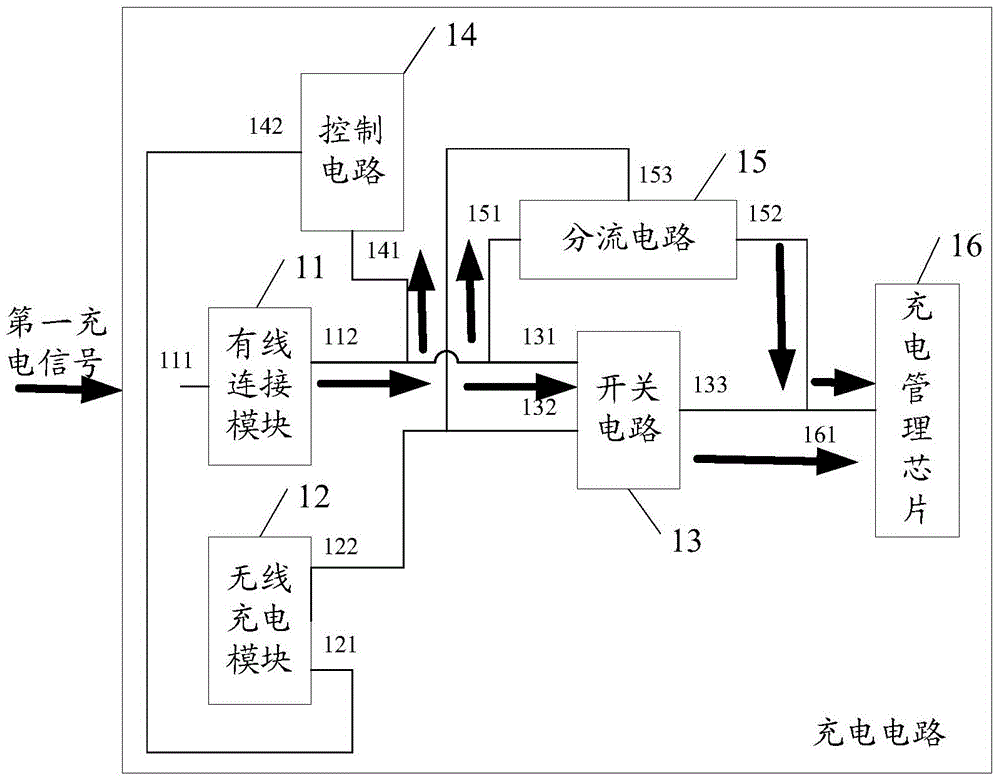
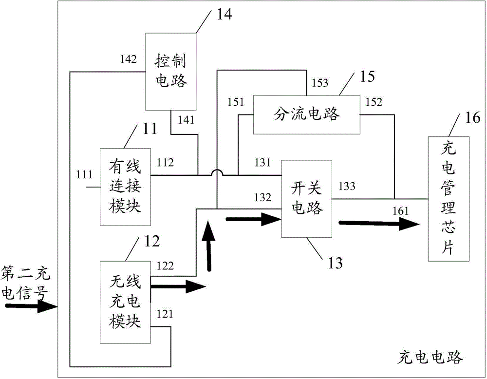
[0042] see figure 1 , figure 1 is a schematic structural diagram of a charging circuit provided by an embodiment of the present invention, such as figure 1 As shown, it includes...


PUM


Abstract

The embodiment of the invention discloses a charging circuit and a terminal. The charging circuit includes a wired connection module, a control circuit, a wireless charging module, a switch circuit, a shunt circuit, and a charging management module. The first input and output end of the wired connection module is used for being connected with the output end of a wired charger. The second input and output end of the wired connection module is connected to the first input end of the switch circuit, and also to the first input and output end of the shunt circuit. The first input end of the control circuit is connected to the second input and output end of the wired connection module. The output end of the control circuit is connected to an enable end of the wireless charging module. The output end of the wireless charging module is connected to the second input end of the switch circuit. The first output end of the switch circuit is connected to the input and output end of the charging management module. The second input and output end of the shunt circuit is connected to the input and output end of the charging management module. The third end of the shunt circuit is connected to the output end of the wireless charging module. The output end of the charging management module is used for being connected to a battery. The problem about technology fusion of a wired charging technology and a wireless charging technology on the terminal is solved.

Description

technical field [0001] The invention relates to the field of electronics, in particular to a charging circuit and a terminal. Background technique [0002] With the development of electronic technology, wireless charging technology has gradually been applied to terminals, such as terminals containing batteries such as mobile phones, tablet computers, or remote control devices. Since the terminal does not need to be connected to the power supply through a cable during the wireless charging process, the user can use the terminal at a place far away from the power supply. However, some users are accustomed to wired charging, some users are accustomed to wireless charging, or the current of the charging signal of wireless charging is too small, resulting in a long battery charging time, etc. Terminal manufacturers often want to configure wired charging and wireless charging for terminals. However, how to integrate wired charging technology and wireless charging technology on th...

Claims


Application Information

Patent Timeline
Patent Type & Authority Applications(China)
IPC IPC(8): H02J7/00
CPCH02J7/0072H02J7/025H02J7/0029H02J7/0036H03K17/122H02J50/10H02J2207/40H02J50/00H02J7/00
Inventor 刘文举彭忠辉杨江涛
Owner HUAWEI DEVICE CO LTD
Why Eureka
Try Eureka