Wireless charging device, charging apparatus and power receiving apparatus

A technology of wireless charging and power receiving equipment, which is applied in the direction of circuit devices, battery circuit devices, current collectors, etc., can solve problems that affect charging efficiency and cannot automatically identify power receiving devices, so as to improve charging efficiency and avoid mutual crosstalk Effect

Active Publication Date: 2016-03-16
SUZHOU QUINGYUE OPTOELECTRONICS TECH CO LTD
View PDF9 Cites 8 Cited by
  • Summary
  • Abstract
  • Description
  • Claims
  • Application Information

AI Technical Summary

Problems solved by technology

This kind of wireless charging device needs to place the receiving device at a specific position on the charging device when charging, and can only realize one-to-one charging, and when replacing the receiving device, it cannot automatically identify the receiving device. The size of the charging current of the electrical equipment changes to a different magnetic field, which affects the charging efficiency

Method used


Image

  • Wireless charging device, charging apparatus and power receiving apparatus

Examples


Embodiment Construction

[0023] In order to further illustrate the technical means and functions adopted by the present invention to achieve the intended purpose of the invention, the present invention will be described in detail below in conjunction with the accompanying drawings and preferred embodiments.

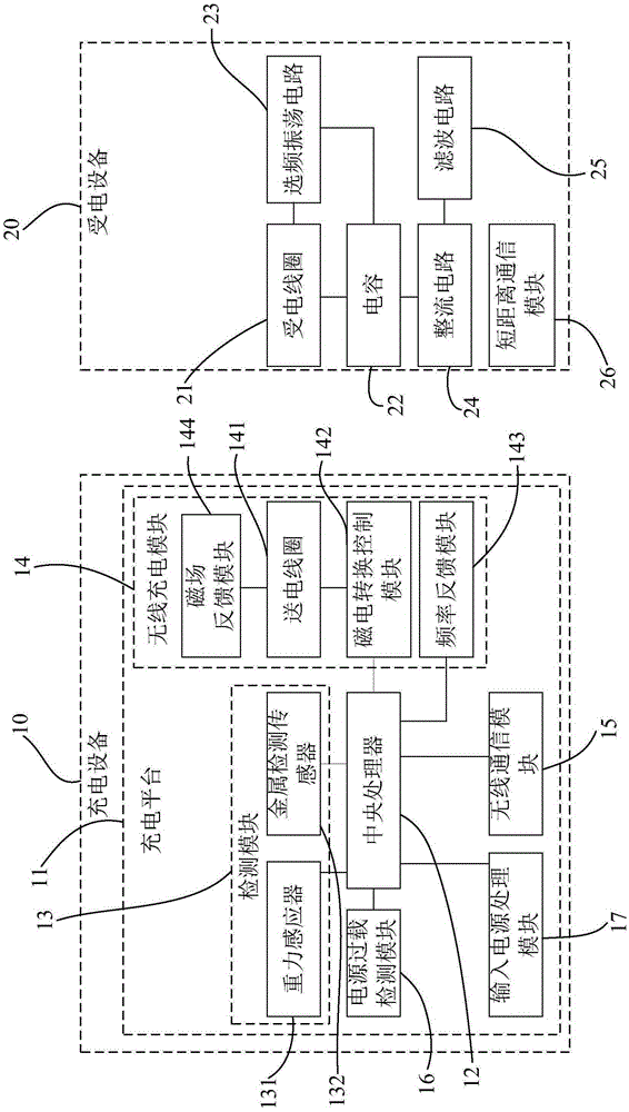
[0024] figure 1 Shown is a schematic diagram of the structure of the wireless charging device provided by the present invention. Such as figure 1 As shown, the wireless charging device of the present invention includes a charging device 10 and a powered device 20 .

[0025] Wherein, the charging device 10 includes a charging platform 11 , a central processing unit 12 , a detection module 13 , a wireless charging module 14 , a wireless communication module 15 , a power overload detection module 16 and an input power processing module 17 . The detection module 13 includes a gravity sensor 131 and a metal detection sensor 132 . The wireless charging module 14 includes a power transmission coil 14...


PUM


Abstract

The invention provides a wireless charging device, a charging apparatus and a power receiving apparatus. The charging apparatus comprises a central processor, a power transmission coil, a magneto-electricity conversion control module and a frequency feedback module. The power receiving apparatus comprises a power reception coil, a capacitor and a frequency-selecting oscillation circuit. The power reception coil and the capacitor compose an LC oscillation circuit. The inherent frequency of the LC oscillation circuit reflects the size of a required charging current. The inherent frequency of the frequency-selecting oscillation circuit is as same as that of the LC oscillation circuit. The central processor controls the power transmission coil to generate an alternating magnetic field so as to drive an alternating current to be generated in the power reception coil; the alternating current after being rectified excites the frequency-selecting oscillation circuit to generate self-exciting oscillation and radiate electromagnetic waves outwards; the frequency feedback module acquires the frequency of the electromagnetic waves and sends the frequency to the central processor; and the central processor controls the magneto-electricity conversion control module to adjust the power transmission coil to generate the alternating magnetic field which matches with a charging current. The charging apparatus can match with different power receiving apparatus to realize intelligent charging.

Description

technical field [0001] The present invention relates to the technical field of wireless charging, in particular to a wireless charging device. Background technique [0002] At present, most of the chargers are connected to the powered equipment through the power cord, and the action of plugging and unplugging the charger plug is required before and after each use, which will inevitably cause the charger plug and the charging interface on the powered equipment to be disconnected. Therefore, after long-term use, poor contact and other phenomena or failures may occur, and it is necessary to go to a special repair shop for repairs, which will cause inconvenience to the use of powered equipment and increase its use cost. [0003] Therefore, the industry has conducted research on the wireless charging technology and obtained certain results. Some wireless charging devices currently on the market use the principle of electromagnetic induction to install induction coils on the char...

Claims


Application Information

Patent Timeline
Patent Type & Authority Applications(China)
IPC IPC(8): H02J7/00H02J50/12
CPCH02J7/025
Inventor 高裕弟孙剑高奇
Owner SUZHOU QUINGYUE OPTOELECTRONICS TECH CO LTD
Why Eureka
Try Eureka