Power generation control device

A control device and power generation control technology, which is applied in the direction of control device, power consumption device, circuit device, etc., can solve the problem of inability to obtain energy balance and other problems, and achieve the effect of improving operation efficiency

Active Publication Date: 2015-06-10
HONDA MOTOR CO LTD
8 Cites 2 Cited by

AI-Extracted Technical Summary

Problems solved by technology

When the state of charge of such a storage battery drops, it may not be possible to achieve energy balance for a low-o...

Method used

[0166] On the other hand, by lowering the threshold value of the vehicle speed VP at which power generation by the auxiliary power unit S is started, power generation is started even in a low vehicle speed state. Thereby, power generation is started even at low vehicle speeds, the SOC of battery 11 can be recovered, and the battery 11 can be prevented from becoming overdischarged even when transitioning to continuous high-load operation. That is, energy control at low vehicle speed and low output can be reliably performed.
[0181] In addition, since the generator power generation output PREQGEN is corrected by the power generation correction amount PGENSLP (see S302) for each vehicle speed and gradient, it is possible to compensate for the influence of the estimated gradient value θ of the road surface (see step S23 in FIG. The power generation amount of the auxiliary power unit S is accurately controlled. Also, since the generator power generation output PREQGEN is corrected by the additional power generation amount PGEN...

Abstract

The purpose of the present invention is to improve the operation efficiency of an internal combustion engine while supplying a required drive force for an electric motor. A power generation control device determines the appropriateness of power generation by a power generator (16) in accordance with the state of a storage battery (11), and when allowing power generation, sets the amount of power generation equivalent to an output required for cruising in accordance with a travelling state, while setting an additional amount of power generation in accordance with the amount of power required depending on a vehicle state and the traveling state. When the amount of power generation and the additional amount of power generation are larger than a maximum amount of power generation, the power generation control device controls the internal combustion engine (15) and the power generator (16) on the basis of the maximum amount of power generation, and when the amount of power generation and the additional amount of power generation are equal to or smaller than the maximum amount of power generation, the power generation control device controls the internal combustion engine (15) and the power generator (16) on the basis of the amount of power generation and the additional amount of power generation.

Application Domain

Hybrid vehiclesBatteries circuit arrangements +16

Technology Topic

Electric generatorEngineering +3

Image

  • Power generation control device
  • Power generation control device
  • Power generation control device

Examples

  • Experimental program(4)

Example

[0057] "First Embodiment"
[0058]
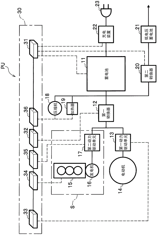
[0059] figure 1 It is a block diagram showing the overall structure of the power unit PU of the vehicle.
[0060] Such as figure 1 As shown, the power unit PU mounted on the vehicle (hybrid motor vehicle) includes a battery 11, a first converter 12, a first power drive unit 13, an electric motor 14, an internal combustion engine 15, a generator 16, a second power drive unit 17, and an electric The compressor 18, the electric heater 19, the second converter 20, the low-voltage battery 21, the charging device 22, the external charging plug 23, and the control device 30. Here, the internal combustion engine 15, the generator 16, and the second power drive unit 17 constitute an auxiliary power unit S that generates electric power by the driving force of the internal combustion engine 15.
[0061] The storage battery 11 is, for example, a lithium ion (Li-ion) secondary battery, and can be charged and discharged.
[0062] One of the first converters 12 is connected to the battery 11, and the other is connected to the first power drive unit 13 and the second power drive unit 17.
[0063] One of the first power drive units 13 is connected to the first converter 12 and the second power drive unit 17, and the other is connected to the electric motor 14.
[0064] The motor 14 is, for example, a three-phase AC brushless motor, and is connected to the first power drive unit 13. It should be noted that although the illustration is omitted, the output shaft (not shown) of the electric motor 14 is connected to the drive shaft (not shown) of the drive wheels (not shown) via a speed change mechanism (not shown) to be connected The rotational driving force of the motor 14 can be transmitted to driving wheels (not shown).
[0065] For example, when the electric motor 14 is driven, the DC power output from the battery 11 is transformed by the first converter 12 and converted into a three-phase AC power by the first power drive unit 13 to be supplied to the electric motor 14. As a result, the vehicle (hybrid vehicle) can be driven.
[0066] On the other hand, for example, when the vehicle (hybrid motor vehicle) is decelerating, driving force is transmitted from the drive shaft (not shown) to the output shaft (not shown) of the electric motor 14, and the electric motor 14 can function as a generator for regenerative power generation. Features. The three-phase AC power output from the electric motor 14 through regenerative power generation is converted into DC power by the first power drive unit 13, and the voltage is transformed by the first converter 12 to be supplied to the battery 11. As a result, the kinetic energy of the vehicle can be converted into electric energy to charge the battery 11.
[0067] The internal combustion engine 15 consumes fuel to rotate a crankshaft (not shown). The crankshaft (not shown) of the internal combustion engine 15 is connected to the rotating shaft (not shown) of the generator 16 via a speed change mechanism (not shown), and is connected so that the rotational driving force of the internal combustion engine 15 can be transmitted to the generator 16.
[0068] The generator 16 is, for example, a three-phase AC brushless motor, and is connected to the second power drive unit 17. In addition, compared to the electric motor 14, the generator 16 uses a small, low-output three-phase AC brushless motor.
[0069] One of the second power drive units 17 is connected to the generator 16, and the other is connected to the first converter 12 and the second power drive unit 17.
[0070] For example, by driving the internal combustion engine 15, a driving force is transmitted from the crankshaft (not shown) to the rotating shaft (not shown) of the generator 16, so that the generator 16 generates power. The three-phase AC power output from the generator 16 is converted into DC power by the second power drive unit 17, and the voltage is transformed by the first converter 12 to be supplied to the battery 11. As a result, fuel can be consumed to charge the battery 11.
[0071] In addition, the second power drive unit 17 can be converted into direct current power, and the first power drive unit 13 can be converted into three-phase alternating current power to be supplied to the electric motor 14.
[0072] The electric compressor 18 is a compressor that constitutes a heat pump circuit that transfers heat between the vehicle interior and the exterior of the vehicle in order to air-condition the vehicle interior. It is connected to the battery 11 and operates with electric power supplied from the battery 11.
[0073] In addition, the electric heater 19 heats the air in the vehicle interior in order to air-condition the vehicle interior, and is connected to the battery 11 and operated by the electric power supplied from the battery 11.
[0074] One of the second converters 20 is connected to the battery 11 and the first converter 12, and the other is connected to the low-voltage battery 21 to step down the power supplied from the battery 11 and/or the first converter 12 (for example, 12V), Therefore, the low-voltage battery 21 can be charged.
[0075] The low-voltage battery 21 has a voltage lower than that of the battery 11 (for example, 12V), and functions as a power source for supplying electric power to the control device 30 and the like.
[0076] It should be noted that, for example, when the state of charge (SOC: State Of Charge) of the battery 11 is reduced, the second converter 20 can boost the power supplied from the low-voltage battery 21, so that the battery 11 can be Recharge.
[0077] One of the charging devices 22 is connected to an external charging plug 23, and the other is connected to the battery 11. The external charging plug 23 can be connected to an external power source (not shown), and the external charging plug 23 is connected to an external power source (for example, a commercial The power supply) is connected, so that the storage battery 11 can be charged.
[0078] The control device 30 is composed of various ECUs (Electronic Control Unit: Electronic Control Unit). The various ECUs are composed of electronic circuits such as a CPU (Central Processing Unit). The control device 30 includes a battery ECU 31, a converter ECU 32, an electric motor ECU 33, and an internal combustion engine ECU 34 , Generator ECU35 and air-conditioning ECU36, each ECU is communicably connected.
[0079] The battery ECU 31 can perform, for example, control of monitoring and protection of the high-voltage electrical system including the battery 11 and control of the power conversion operation of the second converter 20 and the charging device 22. It should be noted that the battery ECU 31 and a voltage sensor (not shown) that detects the voltage of the battery 11, a current sensor (not shown) that detects the current of the battery 11, a temperature sensor (not shown) that detects the temperature of the battery 11, etc. Connected and input the detection signals output from these sensors. In addition, the battery ECU 31 can calculate various state variables such as the remaining power SOC of the battery 11 based on the respective detection signals of the voltage, current, and temperature between the terminals of the battery 11. It should be noted that the charge and discharge current detected by the current sensor can be accumulated to calculate the remaining power SOC, or based on the correlation between the remaining power SOC and the open circuit voltage OCV (Open Circuit Voltage) of the battery 11, the calculation is based on the open circuit voltage OCV Remaining power SOC.
[0080] The converter ECU 32 controls the power conversion operation of the first converter 12 to control the charging and discharging between the battery 11 and the auxiliary power unit S and the electric motor 14.
[0081] The electric motor ECU 33 controls the electric power conversion operation of the first power drive unit 13 so as to control the driving of the electric motor 14 and regenerative power generation.
[0082] The internal combustion engine ECU 34 can control, for example, fuel supply to the internal combustion engine 15 and ignition timing. It should be noted that the internal combustion engine ECU 34 is connected to a cooling water temperature sensor (not shown) or the like that detects the cooling water temperature TW of the internal combustion engine 15, and the detection signals output from these sensors are input.
[0083] The generator ECU 35 controls the power conversion operation of the second power drive unit 17 to control the power generation of the generator 16.
[0084] The air-conditioning ECU 36 controls the operations of the electric compressor 18 and the electric heater 19, thereby being able to control the air conditioning in the vehicle interior.
[0085] In addition, the control device 30 is connected to various sensors (not shown), etc., and receives detection signals output from these sensors.
[0086] The vehicle speed sensor (not shown) detects the vehicle speed VP, which is the speed of the vehicle equipped with the power unit PU, and outputs a detection signal to the control device 30. It should be noted that the control device 30 can calculate the acceleration α of the vehicle based on the difference between the vehicle speed VP and the previous value of the vehicle speed VP.
[0087] The accelerator opening sensor (not shown) detects the amount of depression of the driver's accelerator pedal (not shown), and outputs a detection signal to the control device 30. Then, the control device 30 converts it into the accelerator opening AP based on the detection signal of the depression amount of the accelerator pedal. It should be noted that the amount of depression of the accelerator pedal and the accelerator opening AP can be linear control or non-linear control.
[0088] The brake pedal sensor (not shown) detects whether the driver has stepped on the brake pedal (not shown), and outputs a detection signal to the control device 30.
[0089] A select range sensor (not shown) detects the selected range selected by the driver by operating a gear selector (not shown), and outputs a detection signal to the control device 30.
[0090] The start switch (not shown) is a switch that is pressed when starting the vehicle (hybrid vehicle), and outputs a detection signal to the control device 30.
[0091]
[0092] Next, use figure 2 The operation mode determination processing of the power unit PU of the first embodiment will be described. figure 2 It is a flowchart of the operation mode determination processing of the power unit PU of the first embodiment.
[0093] In step S1, the control device 30 determines whether the selected gear is either P (Park) or N (Neutral) (P or N?). When the selected gear is either the P gear or the N gear (S1 is YES), the processing of the control device 30 proceeds to step S11. On the other hand, when the selected gear is not one of the P range and the N range (S1: No), the processing of the control device 30 proceeds to step S2.
[0094] In step S2, the control device 30 determines whether the driver has stepped on a brake pedal (not shown) (braking?). When the brake pedal is stepped on (Yes in S2), the process of the control device 30 proceeds to step S3. On the other hand, when the brake pedal is not stepped on (S2: No), the process of the control device 30 proceeds to step S21.
[0095] In step S3, the control device 30 determines whether the vehicle speed VP is "0" (VP=0?). When the vehicle speed VP is "0" (Yes in S3), the process of the control device 30 proceeds to step S11. It should be noted that when the process proceeds to step S11, it is the idling time. On the other hand, when the vehicle speed VP is not "0" (NO in S3), the processing of the control device 30 proceeds to step S21.
[0096] In step S11, the control device 30 sets the generator power generation output PREQGEN, which is the power generation amount of the generator 16, to the generator power generation output PREQGENIDL at the idling speed (PREQGEN←PREQGENIDL). It should be noted that the generator power generation output PREQGENIDL at idling speed is a preset setting value and is stored in the control device 30.
[0097] In step S12, the control device 30 sets the rotation speed of the internal combustion engine 15, that is, the engine rotation speed NGEN for generators to the engine rotation speed for generators NGENIDL at idle (NGEN←NGENIDL). It should be noted that the engine rotation speed NGENIDL for the generator at idling speed is a preset setting value and is stored in the control device 30.
[0098] In step S13, the control device 30 determines whether the remaining power SOC of the battery 11 is greater than the power generation implementation upper limit remaining power SOCIDLE at idle (SOC>SOCIDLE?). Here, the power generation implementation upper limit remaining power SOCIDLE during idling is a threshold value set in advance, and is stored in the control device 30. When the remaining power SOC is greater than the power generation implementation upper limit remaining power SOCIDLE at the idling speed (YES in S13), the process of the control device 30 proceeds to step S15. On the other hand, in a case where the remaining power SOC is not greater than the power generation implementation upper limit remaining power SOCIDLE during idling (No in S13), the processing of the control device 30 proceeds to step S14.
[0099] In step S14, control device 30 sets the operation mode of power unit PU to the first mode (REV IDLE), and ends the operation mode determination process of power unit PU.
[0100] Here, the first mode (REV IDLE) is a mode in which power generation by the auxiliary power unit S is performed in a state where the electric motor 14 is stopped. Thereby, the electric power generated by the auxiliary power unit S is charged to the battery 11, and the remaining power SOC of the battery 11 is increased. Specifically, the motor ECU 33 controls the first power drive unit 13 to stop the motor 14 (MOT: stop). The internal combustion engine ECU 34 controls the internal combustion engine 15 (ENG:ON) so that the rotation speed of the internal combustion engine 15 becomes the generator engine rotation speed NGEN (that is, the generator engine rotation speed NGENIDL at idle) set in step S12. The generator ECU 35 controls the second power drive unit 17 (GEN: power generation) so that the power generation amount of the generator 16 becomes the generator power generation output PREQGEN (ie, the generator power generation output PREQGENIDL at idle) set in step S11 . The converter ECU 32 controls the first converter 12 to charge the battery 11 with electric power generated by the auxiliary power unit S. The battery ECU 31 monitors and protects the battery 11.
[0101] In step S15, control device 30 sets the operation mode of power unit PU to the second mode (IDLE STOP), and ends the operation mode determination process of power unit PU.
[0102] Here, the second mode (IDLE STOP) is a mode in which the auxiliary power unit S is stopped (not generating power) in a state where the electric motor 14 is stopped. Specifically, the motor ECU 33 controls the first power drive unit 13 to stop the motor 14 (MOT: stop). The internal combustion engine ECU 34 controls the internal combustion engine 15 to stop the internal combustion engine 15 (ENG: OFF). The generator ECU 35 controls the second power drive unit 17 to stop the generator 16 (GEN: stop).
[0103] In step S21, the control device 30 performs a map search on the required driving force FREQF of the electric motor 14 based on the vehicle speed VP and the accelerator opening AP (FREQF←MAP search based on VP and AP). Here, the required driving force FREQF refers to the driving force generated by the electric motor 14 requested by the driver. It should be noted that the map of the required driving force FREQF with respect to the vehicle speed VP and the accelerator opening AP is stored in the control device 30 in advance. In addition, the map of the required driving force FREQF may be set such that, for example, when the vehicle speed VP is equal to or higher than the predetermined vehicle speed, as the vehicle speed VP increases, the required driving force FREQF decreases. In addition, for example, when the vehicle speed is low (vehicle speed VP is less than the predetermined vehicle speed) and the accelerator opening AP is around 0, the driving force may be negative (ie, regeneration), so it is set to increase as the accelerator opening AP , The driving force FREQF is required to be close to zero.
[0104] In step S22, the control device 30 calculates the required drive output PREQ of the electric motor 14 based on the vehicle speed VP and the required drive force FREQF obtained in step S21 (PREQ←calculated from VP and FREQF). Here, the required driving output PREQ refers to the electric power output from the battery 11 (and/or the auxiliary power unit S) to the electric motor 14 in order to cause the electric motor 14 to generate the required driving force FREQF obtained in step S21. It should be noted that the calculation formula of the required drive output PREQ is determined by the characteristics of the electric motor 14 and is stored in the control device 30 in advance.
[0105] In step S23, the control device 30 calculates an estimated gradient value θ based on the vehicle speed VP, acceleration α, and the previous value of the required driving force FREQF, that is, the required driving force (previous value) FREQFB (calculate the gradient based on VP, α, FREQFB) Estimated value θ). Here, the estimated gradient value θ refers to an estimated value of the gradient of the road surface on which the vehicle equipped with the power unit PU is currently traveling.
[0106] In addition, the gradient estimation value θ is calculated by Equation (1) based on the required driving force (previous value) FREQFB, air resistance Ra, rolling resistance Rr, acceleration resistance Rc, vehicle weight W, and gravitational acceleration g. It should be noted that the air resistance Ra is calculated by equation (2) based on the air resistance coefficient λ, the front projection area S, and the vehicle speed VP. The rolling resistance Rr is calculated by equation (3) based on the vehicle weight W and the rolling resistance coefficient μ. The acceleration resistance Rc is calculated by equation (4) based on the acceleration α and the vehicle weight W. It should be noted that the gravitational acceleration g, the air resistance coefficient λ, the front projection area S, the vehicle weight W, and the rolling resistance coefficient μ are preset values ​​and are stored in the control device 30.
[0107] [Number 1]
[0108] θ = [ FREQFB - ( Ra + Rr + Rc ) ] W X g . . . ( 1 )
[0109] Ra=λ×S×VP 2 ···(2)
[0110] Rr=W×μ ···(3)
[0111] Rc=α×W ···(4)
[0112] In step S24, the control device 30 calculates the depth of discharge DOD of the battery 11 (calculates the depth of discharge). use image 3 The details will be described later.
[0113] In step S25, the control device 30 determines whether to perform power generation by the auxiliary power unit S (power generation performance determination). That is, a flag to perform power generation by the auxiliary power unit S (power generation implementation flag F_GEN described below is F_GEN = 1) or not perform power generation by the auxiliary power unit S (power generation implementation flag F_GEN described below is F_GEN = 0) deal with. use Figure 4 The details will be described later.
[0114] In step S26, the control device 30 calculates the power generation amount of the generator 16, that is, the generator power generation output PREQGEN (calculated power generation amount). use Figure 5 The details will be described later.
[0115] In step S27, the control device 30 performs limit processing (power generation limit processing) on ​​the generator power generation output PREQGEN calculated in step S26. use Image 6 The details will be described later.
[0116] In step S28, the control device 30 performs a catalog search on the rotation speed of the internal combustion engine 15, that is, the engine rotation speed NGEN for generator, based on the generator power generation output PREQGEN after the limit processing in step S27 (NGEN← catalog search based on PREQGEN ). It should be noted that a list of the engine rotation speed NGEN for the generator with respect to the generator power generation output PREQGEN is stored in the control device 30 in advance. In addition, such as figure 2 As shown, in this catalog, as the generator power generation output PREQGEN increases, the engine rotation speed NGEN for the generator increases.
[0117] In step S29, the control device 30 determines whether the required driving force FREQF of the electric motor 14 obtained in step S21 is less than "0" (FREQF<0?). If the required driving force FREQF is less than "0" (Yes in S29), the process of the control device 30 proceeds to step S30. On the other hand, in a case where the required driving force FREQF is not less than "0" (No in S29), the processing of the control device 30 proceeds to step S33.
[0118] In step S30, the control device 30 determines whether the power generation execution flag F_GEN obtained in step S25 is "1" (GEN: power generation) (F_GEN=1?). When the power generation execution flag F_GEN is "1" (GEN: power generation) (Yes in S30), the processing of the control device 30 proceeds to step S32. On the other hand, when the power generation execution flag F_GEN is not "1" (GEN: power generation) (NO in S30), the process of the control device 30 proceeds to step S31.
[0119] In step S31, control device 30 sets the operation mode of power unit PU to the third mode (EV REGEN), and ends the operation mode determination process of power unit PU.
[0120] Here, the third mode (EV REGEN) is a mode in which the auxiliary power unit S is stopped (not generating power) in a state where the electric motor 14 is regeneratively generated. Thereby, the electric power regenerated and generated by the electric motor 14 is charged to the battery 11, and the remaining power SOC of the battery 11 is increased. Specifically, the motor ECU 33 makes the drive force of the electric motor 14 the required drive force FREQF obtained in step S21 (so that the output of the regenerative power generation of the electric motor 14 becomes the required drive output PREQ obtained in step S22). Mode) to control the first power drive unit 13 (MOT: Regeneration). The internal combustion engine ECU 34 controls the internal combustion engine 15 to stop the internal combustion engine 15 (ENG: OFF). The generator ECU 35 controls the second power drive unit 17 to stop the generator 16 (GEN: stop). The converter ECU 32 controls the first converter 12 so as to charge the battery 11 with electric power regenerated and generated by the electric motor 14. The battery ECU 31 monitors and protects the battery 11.
[0121] In step S32, control device 30 sets the operation mode of power unit PU to the fourth mode (REV REGEN), and ends the operation mode determination process of power unit PU.
[0122] Here, the fourth mode (REV REGEN) is a mode in which power generation by the auxiliary power unit S is performed in a state where the electric motor 14 is regeneratively generated. Thereby, the electric power regeneratively generated by the electric motor 14 and the electric power generated by the auxiliary power unit S are charged to the battery 11, and the remaining power SOC of the battery 11 is increased. Specifically, the motor ECU 33 makes the drive force of the electric motor 14 the required drive force FREQF obtained in step S21 (so that the output of the regenerative power generation of the electric motor 14 becomes the required drive output PREQ obtained in step S22). Mode) to control the first power drive unit 13 (MOT: Regeneration). The internal combustion engine ECU 34 controls the internal combustion engine 15 (ENG: ON) so that the rotation speed of the internal combustion engine 15 becomes the generator engine rotation speed NGEN obtained in step S28. The generator ECU 35 controls the second power drive unit 17 (GEN: power generation) so that the power generation amount of the generator 16 becomes the generator power generation output PREQGEN obtained in step S26 and step S27. The converter ECU 32 controls the first converter 12 to charge the battery 11 with the electric power regeneratively generated by the electric motor 14 and the electric power generated by the auxiliary power unit S. The battery ECU 31 monitors and protects the battery 11.
[0123] In step S33, the control device 30 determines whether the power generation execution flag F_GEN obtained in step S25 is "1" (GEN: power generation) (F_GEN=1?). When the power generation execution flag F_GEN is "1" (GEN: power generation) (Yes in S33), the processing of the control device 30 proceeds to step S34. On the other hand, when the power generation execution flag F_GEN is not "1" (GEN: power generation) (NO in S33), the process of the control device 30 proceeds to step S35.
[0124] In step S34, control device 30 sets the operation mode of power unit PU to the fifth mode (REV RUN), and ends the operation mode determination process of power unit PU.
[0125] Here, the fifth mode (REV RUN) is a mode in which power generation by the auxiliary power unit S is performed, and the electric motor 14 is driven by the electric power generated by the auxiliary power unit S and/or the electric power stored in the battery 11 to perform traveling. As a result, when the electric power consumed by the electric motor 14 is greater than the electric power generated by the auxiliary power unit S, the reduction amount of the remaining power SOC of the battery 11 is reduced. In addition, when the electric power consumed by the electric motor 14 is less than the electric power generated by the auxiliary power unit S, a part of the electric power generated by the auxiliary power unit S is charged to the battery 11 to increase the remaining power SOC of the battery 11. Specifically, the motor ECU 33 makes the driving force of the electric motor 14 equal to the required drive force FREQF obtained in step S21 (so that the electric power supplied to the electric motor 14 becomes the value of the required drive output PREQ obtained in step S22). Method) Control the first power drive unit 13 (MOT: Drive). The internal combustion engine ECU 34 controls the internal combustion engine 15 (ENG: ON) so that the rotation speed of the internal combustion engine 15 becomes the generator engine rotation speed NGEN obtained in step S28. The generator ECU 35 controls the second power drive unit 17 (GEN: power generation) so that the power generation amount of the generator 16 becomes the generator power generation output PREQGEN obtained in step S26 and step S27. The converter ECU 32 controls the first converter 12 to supply the electric power generated by the auxiliary power unit S and/or the electric power stored in the battery 11 to the electric motor 14. The battery ECU 31 monitors and protects the battery 11.
[0126] In step S35, control device 30 sets the operation mode of power unit PU to the sixth mode (EV RUN), and ends the operation mode determination process of power unit PU.
[0127] Here, the sixth mode (EV RUN) is a mode in which the electric motor 14 is driven by the electric power stored in the battery 11 and the auxiliary power unit S is stopped (not generating power). Thereby, it is possible to travel with the electric power stored in the battery 11 without consuming the fuel of the internal combustion engine 15. Specifically, the motor ECU 33 makes the driving force of the electric motor 14 equal to the required drive force FREQF obtained in step S21 (so that the electric power supplied to the electric motor 14 becomes the value of the required drive output PREQ obtained in step S22). Method) Control the first power drive unit 13 (MOT: Drive). The internal combustion engine ECU 34 controls the internal combustion engine 15 to stop the internal combustion engine 15 (ENG: OFF). The generator ECU 35 controls the second power drive unit 17 to stop the generator 16 (GEN: OFF). The converter ECU 32 controls the first converter 12 so that the electric power generated by the auxiliary power unit S and/or the electric power stored in the battery 11 is supplied to the electric motor 14. The battery ECU 31 monitors and protects the battery 11.
[0128]
[0129] Next, use image 3 , The depth of discharge calculation process in step S24 will be described. image 3 It is a flowchart of the depth of discharge calculation process.
[0130] In step S101, the control device 30 determines whether it is when the start switch is turned on (start SW ON?). Here, "when the start switch is turned on" refers to the first calculation time after the start switch is pressed. When the start switch is turned on (Yes in S101), the process of the control device 30 proceeds to step S102. On the other hand, when it is not when the start switch is turned on (No in S101), the processing of the control device 30 proceeds to step S109.
[0131] In step S102, the control device 30 sets the depth-of-discharge calculation reference remaining power SOCINT to the remaining power SOC of the battery 11 (SOCINT←SOC).
[0132] In step S103, the control device 30 determines whether the depth-of-discharge calculation reference remaining power SOCINT is less than the lower limit value of the depth-of-discharge calculation reference remaining power SOTINTL (SOCINT
[0133] In step S104, the control device 30 sets the depth-of-discharge calculation reference remaining power SOCINT as the depth-of-discharge calculation reference remaining power lower limit SOTINTL (SOCINT←SOCINTL). Then, the processing of the control device 30 proceeds to step S105.
[0134] In step S105, the control device 30 sets the depth-of-discharge calculation implementation lower limit threshold SOCLMTL to a value obtained by subtracting the depth-of-discharge calculation implementation judgment discharge amount DODLMT from the depth-of-discharge calculation reference remaining power SOCINT (SOCLMTL←SOCINT-DODLMT). It should be noted that the depth of discharge calculation is implemented to determine the discharge amount DODLMT (refer to Figure 7 ) Is a preset setting value and is stored in the control device 30.
[0135] In step S106, the control device 30 sets the depth-of-discharge calculation implementation upper limit threshold SOCLMTH to a value obtained by adding the depth-of-discharge calculation implementation judgment charge amount SOCUP to the depth-of-discharge calculation reference remaining power SOCINT (SOCLMTH←SOCINT+SOCUP). It should be noted that the depth of discharge calculation is implemented to determine the charge amount SOCUP (refer to Figure 7 ) Is a preset setting value and is stored in the control device 30.
[0136] In step S107, the control device 30 sets the discharge depth calculation implementation flag F_DODLMT to "0" (not implemented) (F_DODLMT←0).
[0137] In step S108, the control device 30 sets the depth of discharge DOD to the initial value "0" (DOD←0), ends the depth of discharge calculation process (step S24), and proceeds to step S25 (refer to figure 2 ).
[0138] In addition, in step S109, the control device 30 determines whether the remaining power SOC is greater than the discharge depth calculation implementation upper limit remaining power SOCUPH (SOC>SOCUPH?). Here, the depth-of-discharge calculation implementation upper limit remaining power SOCUPH is a preset threshold value and is stored in the control device 30. In the case where the remaining power SOC is greater than the depth of discharge calculation implementation upper limit remaining power SOCUPH (YES in S109), the processing of the control device 30 proceeds to step S107. On the other hand, in the case where the remaining power SOC is not greater than the depth-of-discharge calculation implementation upper limit remaining power SOCUPH (No in S109), the processing of the control device 30 proceeds to step S110.
[0139] In step S110, the control device 30 determines whether the remaining power SOC is greater than the discharge depth calculation implementation lower limit threshold SOCLMTL (refer to step S105) (SOC>SOCLMTL?). When the remaining power SOC is greater than the depth-of-discharge calculation implementation lower limit threshold SOCLMTL (YES in S110), the process of the control device 30 proceeds to step S113. On the other hand, when the remaining power SOC is not greater than the depth-of-discharge calculation implementation lower limit threshold SOCLMTL (No in S110), the processing of the control device 30 proceeds to step S111.
[0140] In step S111, the control device 30 sets the discharge depth calculation implementation flag F_DODLMT to "1" (implementation) (F_DODLMT←1).
[0141] In step S112, the control device 30 sets the depth of discharge DOD to the value obtained by subtracting the remaining power SOC from the reference remaining power SOCINT for the depth of discharge calculation (DOD←SOCINT-SOC), and ends the depth of discharge calculation process (step S24), and Proceed to step S25 (refer to figure 2 ).
[0142] In step S113, the control device 30 determines whether the depth-of-discharge calculation implementation flag F_DODLMT is "1" (implementation) (F_DODLMT=1?). When the depth-of-discharge calculation implementation flag F_DODLMT is "1" (implemented) (YES in S113), the process of the control device 30 proceeds to step S114. On the other hand, when the depth-of-discharge calculation implementation flag F_DODLMT is not "1" (implemented) (NO in S113), the depth-of-discharge calculation process is ended (step S24), and the process proceeds to step S25 (refer to figure 2 ).
[0143] In step S114, control device 30 determines whether the remaining power SOC is greater than the depth-of-discharge calculation implementation upper limit threshold SOCLMTH (refer to step S106) (SOC>SOCLMTH?). When the remaining power SOC is greater than the depth-of-discharge calculation implementation upper limit threshold SOCLMTH (Yes in S114), the process of the control device 30 proceeds to step S102. On the other hand, in a case where the remaining power SOC is not greater than the depth-of-discharge calculation implementation upper limit threshold SOCLMTH (No in S114), the process of the control device 30 proceeds to step S115.
[0144] In step S115, the control device 30 sets the depth of discharge DOD to the value obtained by subtracting the remaining power SOC from the reference remaining power SOCINT for the depth of discharge calculation (DOD←SOCINT-SOC), ends the depth of discharge calculation process (step S24), and Proceed to step S25 (refer to figure 2 ).
[0145] (Operation example of depth of discharge calculation processing)
[0146] Here, use Figure 7 , The operation example of the depth-of-discharge calculation processing will be described. Figure 7 It is a graph explaining the depth-of-discharge calculation process, the horizontal axis is time, and the vertical axis is the ratio (%) of the remaining power SOC of the battery 11.
[0147] First, when the start switch is turned on ( Figure 7 Point A), read the remaining power SOC of the battery 11 and set it as the depth of discharge calculation reference remaining power SOCINT (refer to image 3 The S101 is yes, S102). In addition, the lower limit threshold SOCLMTL for depth of discharge calculation and the upper limit threshold SOCLMTH for depth of discharge calculation are calculated based on the reference remaining power SOCINT for the depth of discharge calculation (refer to image 3 S105, S106), and initialize the discharge depth calculation implementation flag F_DODLMT and discharge depth DOD (refer to image 3 S107, S108).
[0148] It should be noted that although with Figure 7 The example is different, but the depth-of-discharge calculation reference remaining power SOCINT has a lower limit. When the remaining power SOC is less than the lower limit of the depth-of-discharge calculation reference remaining power SOCITL, set the lower limit of the depth-of-discharge calculation reference remaining power SOTINTL to SOCINT (reference image 3 The S103 is yes, S104). Thus, the threshold for starting the calculation of the depth of discharge DOD, that is, the lower limit of the depth of discharge calculation implementation threshold SOCLMTL also has a lower limit value (SOCINTL-DODLMT). Therefore, for example, when the remaining power SOC of the battery 11 is low when the start switch is turned on, the Able to start the calculation of the depth of discharge DOD. In addition, the depth of discharge DOD can be increased compared to the case where the remaining power SOC that is less than the lower limit value of the lower limit value of the depth of discharge calculation reference remaining power SOCITL is used as the reference remaining power SOCINT of the depth of discharge calculation. As a result, as will be described later, the judgment processing (especially referring to Figure 4 In S203), it is controlled in a way that can be easily judged as the start of power generation, and the power generation calculation process (especially refer to Figure 5 S304) can be controlled in the direction of increasing the amount of power generation. This can prevent the battery 11 from becoming over-discharged.
[0149] back to Figure 7 In the example, before the remaining power SOC of the battery 11 becomes the lower limit threshold SOCLMTL of the depth of discharge calculation ( Figure 7 From point A to point B), the depth of discharge DOD is not calculated, and the depth of discharge DOD remains at "0" (refer to S110 for YES, S113 for NO).
[0150] When the remaining power SOC of the battery 11 becomes the lower limit threshold SOCLMTL for the depth of discharge calculation ( Figure 7 Point B), that is, when the remaining power SOC is moved from the depth-of-discharge calculation reference remaining power SOCINT to the state after the depth-of-discharge calculation is performed to determine the amount of discharge DODLMT, the calculation of the depth-of-discharge DOD is started (refer to S110 for No, S111) . Then, before the remaining power SOC of the battery 11 becomes greater than the depth-of-discharge calculation implementation upper limit threshold SOCLMTH ( Figure 7 From point B to point C), start the calculation of the depth of discharge DOD (see S112, S115).
[0151] When the remaining power SOC of the battery 11 is greater than the upper limit threshold SOCLMTH for calculating the depth of discharge ( Figure 7 C point), that is, when the remaining power SOC is restored from the depth-of-discharge calculation reference remaining power SOCINT to the state where the upper-limit threshold SOCLMTH for the depth-of-discharge calculation is implemented (see S114 for YES), the calculation of the depth-of-discharge DOD ends (see S107 and S108 ), and update the depth-of-discharge calculation reference remaining power SOCINT (refer to S102 to S104).
[0152] It should be noted that although with Figure 7 The example is different, but when the remaining power SOC of the battery 11 is greater than the upper limit remaining power SOCUPH for the depth of discharge calculation, the reference remaining power SOCINT for the depth of discharge calculation is not updated, and the depth of discharge DOD is set to "0" to end the calculation (see S109 for Yes, S107, S108). That is, when there is a margin in the remaining power SOC of the battery 11, the depth of discharge DOD is not calculated.
[0153]
[0154] Next, use Figure 4 , The power generation implementation judgment processing in step S25 will be described. Figure 4 It is a flowchart of power generation execution judgment processing.
[0155] In step S201, the control device 30 determines whether the remaining power SOC is less than the REV mode power generation implementation upper limit remaining power SOCREV (SOC
[0156] In step S202, the control device 30 determines whether the cooling water temperature TW of the internal combustion engine 15 is higher than the EV mode implementation upper limit water temperature TWEV (TW>TWEV?). Here, the EV mode implementation upper limit water temperature TWEV refers to a threshold value for determining whether the internal combustion engine 15 is warmed up. The control device 30 does not perform power generation by the generator 16 until the warm-up of the internal combustion engine 15 is completed. When the cooling water temperature TW is higher than the EV mode implementation upper limit water temperature TWEV (that is, when the warm-up is completed) (YES in S202), the process of the control device 30 proceeds to step S203. On the other hand, when the cooling water temperature TW is not higher than the EV mode implementation upper limit water temperature TWEV (that is, when the warm-up is not completed) (NO in S202), the processing of the control device 30 proceeds to step S208.
[0157] In step S203, the control device 30 performs a catalog search for the power generation implementation lower limit vehicle speed VPGENDOD determined based on the discharge depth DOD (VPGENDOD←DOD-based catalog search). Here, the power generation implementation lower limit vehicle speed VPGENDOD determined based on the depth of discharge refers to a threshold for determining whether to implement power generation by the auxiliary power unit S based on the vehicle speed VP (refer to step S205 described later). It should be noted that a list of the power generation implementation lower limit vehicle speed VPGENDOD determined based on the depth of discharge relative to the depth of discharge DOD is stored in the control device 30 in advance. In addition, such as Figure 4 As shown, in this catalog, when the depth of discharge DOD becomes larger than the predetermined value, as the depth of discharge DOD becomes larger, the lower limit vehicle speed VPGENDOD determined for power generation based on the depth of discharge becomes smaller.
[0158] In step S204, the control device 30 performs a catalog search for the power generation implementation lower limit vehicle speed VPGENSOC determined based on the remaining power based on the remaining power SOC (VPGENSOC ← SOC-based catalog search). Here, the power generation implementation lower limit vehicle speed VPGENSOC determined based on the remaining power is a threshold value for determining whether to implement power generation by the auxiliary power unit S based on the vehicle speed VP (refer to step S206 described later). It should be noted that a list of the power generation implementation lower limit vehicle speed VPGENSOC determined based on the remaining power amount relative to the remaining power amount SOC is stored in the control device 30 in advance. In addition, such as Figure 4 As shown, in this catalog, when the remaining power SOC becomes smaller than a predetermined value, as the remaining power SOC decreases, the power generation implementation lower limit vehicle speed VPGENSOC determined based on the remaining power decreases.
[0159] In step S205, the control device 30 determines whether the vehicle speed VP is greater than the power generation implementation lower limit vehicle speed VPGENDOD determined based on the depth of discharge (refer to step S203) (VP>VPGENDOD?). In a case where the vehicle speed VP is greater than the power generation implementation lower limit vehicle speed VPGENDOD determined based on the depth of discharge (YES in S205), the processing of the control device 30 proceeds to step S207. On the other hand, in a case where the vehicle speed VP is not greater than the power generation implementation lower limit vehicle speed VPGENDOD determined based on the depth of discharge (NO in S205), the processing of the control device 30 proceeds to step S206.
[0160] In step S206, the control device 30 determines whether the vehicle speed VP is greater than the power generation implementation lower limit vehicle speed VPGENSOC determined based on the remaining power (refer to step S204) (VP>VPGENSOC?). In a case where the vehicle speed VP is greater than the power generation implementation lower limit vehicle speed VPGENSOC determined based on the remaining power (YES in S206), the process of the control device 30 proceeds to step S207. On the other hand, in a case where the vehicle speed VP is not greater than the power generation implementation lower limit vehicle speed VPGENSOC determined based on the remaining power (NO in S206), the processing of the control device 30 proceeds to step S208.
[0161] In step S207, the control device 30 sets the power generation execution flag F_GEN to "1" (GEN: power generation) (F_GEN←1). Then, the power generation implementation judgment process is ended (step S25), and the process proceeds to step S26 (refer to figure 2 ).
[0162] In step S208, the control device 30 sets the power generation execution flag F_GEN to "0" (GEN: stop) (F_GEN←0). Then, the power generation implementation judgment process is ended (step S25), and the process proceeds to step S26 (refer to figure 2 ).
[0163] such, Figure 4 When the depth of discharge DOD increases, or when the remaining power SOC decreases, that is, when the battery 11 may become over-discharged, the power generation execution judgment processing shown is reduced by reducing the threshold value of the vehicle speed VP at which power generation by the auxiliary power unit S is started (based on The power generation implementation lower limit vehicle speed VPGENDOD determined based on the depth of discharge, and the power generation implementation lower limit vehicle speed VPGENSOC determined based on the remaining power can prevent the battery 11 from becoming over-discharged.
[0164] For example, even if loads such as air conditioners and heaters that are not related to the conditions of the running load are operated, the remaining power SOC of the battery 11 decreases (and/or the depth of discharge DOD also increases). In a conventional power generation control device equipped with a relatively high-output generator (internal combustion engine), in a low-vehicle speed state where the vehicle speed VP is below a predetermined threshold value, it will not be used until the remaining power SOC of the battery 11 becomes below the predetermined value. Start generating electricity. Even so, since a relatively high-output generator (internal combustion engine) is provided, the output requirement of the electric motor 14 can be satisfied even if the battery 11 is continuously high-load operation (for example, traveling on an uphill road) while the remaining power SOC of the battery 11 is reduced.
[0165] On the other hand, in the case of a low-output generator 16 (an internal combustion engine 15 with a small displacement), the low-output generator 16 is used when the high-load operation is continued while the remaining power SOC of the battery 11 is lowered. (The internal combustion engine 15 with a small displacement) cannot satisfy the output requirement of the electric motor 14, and the battery 11 may become over-discharged.
[0166] In contrast to this, by lowering the threshold value of the vehicle speed VP at which power generation by the auxiliary power unit S is started, power generation is started even in a low vehicle speed state. Thereby, power generation is started even in a low vehicle speed state, the remaining power SOC of the battery 11 can be restored, and even in the case of transition to continuous high-load operation, the battery 11 can be prevented from becoming an overdischarged state. That is, it is possible to reliably perform energy control at low vehicle speed and low output.
[0167]
[0168] Next, use Figure 5 The power generation calculation processing in step S26 will be described. Figure 5 It is a flowchart of the power generation amount calculation process of the first embodiment.
[0169] In step S301, based on the vehicle speed VP, the control device 30 performs a catalog search for the power generation amount PGENRL corresponding to the output required for cruising at each vehicle speed (PGENRL← catalog search based on VP). Here, the power generation amount PGENRL equivalent to the output required for cruising at each vehicle speed is the electric power supplied to the electric motor 14 for the electric motor 14 to generate a driving force that overcomes only the air resistance Ra and the rolling resistance Rr of the vehicle. It should be noted that a list of the power generation amount PGENRL corresponding to the output required for cruise at each vehicle speed with respect to the vehicle speed VP is stored in the control device 30 in advance. In addition, such as Figure 5 As shown, in this catalog, as the vehicle speed VP becomes larger, the power generation amount PGENR required for cruise at each vehicle speed becomes larger.
[0170] In step S302, the control device 30 is based on the vehicle speed VP and the road gradient estimated value θ (refer to figure 2 Step S23) to perform a map search for the power generation correction amount PGENSLP for each vehicle speed and gradient (PGENSLP←MAP search based on VP and θ). It should be noted that the mapping of the power generation correction amount PGENSLP for each vehicle speed and gradient with respect to the vehicle speed VP and the gradient estimated value θ is stored in the control device 30 in advance. In addition, the mapping of the power generation correction amount PGENSLP for each vehicle speed and the gradient can be set such that as the estimated gradient value θ becomes larger, the power generation correction amount PGENSLP becomes larger, and when the estimated gradient value θ is constant, it follows the vehicle speed VP As it becomes larger, the power generation correction amount PGENSLP becomes smaller.
[0171] In step S303, the control device 30 performs a catalog search for the additional basic amount of power generation PGENBASE at each vehicle speed based on the vehicle speed VP (PGENBASE← catalog search based on VP). It should be noted that a list of the additional basic amount of power generation PGENBASE relative to the vehicle speed VP at each vehicle speed is stored in the control device 30 in advance. In addition, such as Figure 5 As shown, in this catalog, as the vehicle speed VP becomes larger, the additional basic amount of power generation PGENBASE at each vehicle speed becomes smaller.
[0172] In step S304, the control device 30 performs a map search (PGENDOD←MAP search based on VP and DOD) on the additional power generation amount PGENDOD for each vehicle speed and depth of discharge based on the vehicle speed VP and the depth of discharge DOD. It should be noted that the mapping of the additional power generation amount PGENDOD for each vehicle speed and depth of discharge with respect to the vehicle speed VP and depth of discharge DOD is stored in the control device 30 in advance. In addition, the mapping of the additional power generation amount PGENDOD for each vehicle speed and the depth of discharge can be set such that as the depth of discharge DOD increases, the additional amount of power generation PGENDOD increases, and when the depth of discharge DOD is constant, it changes with the vehicle speed VP. Larger, the additional power generation amount PGENDOD becomes smaller.
[0173] In step S305, the control device 30 performs a map search for the additional power generation amount PGENSOC for each vehicle speed and the remaining power based on the vehicle speed VP and the remaining power SOC (PGENSOC←MAP search based on VP and SOC). It should be noted that the mapping of the additional power generation amount PGENSOC for each vehicle speed and the remaining power to the vehicle speed VP and the remaining power SOC is stored in the control device 30 in advance. In addition, the mapping between each vehicle speed and the additional power generation amount PGENSOC of the remaining power can be set such that, for example, as the remaining power SOC becomes smaller, the additional power generation amount PGENSOC becomes larger. In the case where the remaining power SOC is constant, the additional power generation amount PGENSOC becomes larger. Larger, the additional power generation amount PGENSOC becomes smaller.
[0174] In step S306, based on the vehicle speed VP, the control device 30 performs a catalog search (PGENAC ← catalog search based on VP) for the additional power generation amount PGENAC at the time of air conditioning use for each vehicle speed. It should be noted that a list of the additional power generation amount PGENAC at the time of air conditioning use for each vehicle speed relative to the vehicle speed VP is stored in the control device 30 in advance. In addition, such as Figure 5 As shown, in this catalog, as the vehicle speed VP increases, the additional power generation amount PGENAC during air conditioning use at each vehicle speed decreases.
[0175] In step S307, the control device 30 determines whether the air-conditioning use flag F_AC is "1" (air-conditioning is used) (F_AC=1?). It should be noted that when the electric compressor 18 and/or the electric heater 19 are operating, the air-conditioning ECU 36 sets the air-conditioning use flag F_AC to "1" (air conditioning is used), and does not operate the electric compressor 18 and the electric heater 19 When the air conditioner use flag F_AC is "0" (air conditioner is not used). When the air-conditioning use flag F_AC is "1" (air-conditioning is used) (Yes in S307), the process of the control device 30 proceeds to step S309. On the other hand, when the air-conditioning use flag F_AC is not "1" (air-conditioning is used) (No in S307), the processing of the control device 30 proceeds to step S308.
[0176] In step S308, the control device 30 sets the power generation output of the generator 16, that is, the generator power generation output PREQGEN to the power generation PGENRL (refer to S301) equivalent to the output required for cruise at each vehicle speed, and the power generation correction for each vehicle speed and gradient PGENSLP (refer to S302), additional basic power generation amount PGENBASE (refer to S303) at each vehicle speed, additional power generation amount PGENDOD (refer to S304) for each vehicle speed and depth of discharge, and additional power generation amount PGENSOC (refer to S305) for each vehicle speed and remaining power The added value. Then, the power generation amount calculation process is ended (step S26), and the process proceeds to step S27 (refer to figure 2 ).
[0177] In step S309, the control device 30 sets the power generation output PREQGEN of the generator 16, which is the power generation output PREQGEN, to the power generation PGENRL (refer to S301) equivalent to the output required for cruise at each vehicle speed, and the power generation correction for each vehicle speed and gradient PGENSLP (refer to S302), additional basic power generation amount PGENBASE (refer to S303) at each vehicle speed, additional power generation amount PGENDOD for each vehicle speed and depth of discharge (see S304), additional power generation amount PGENSOC (see S305) for each vehicle speed and remaining power And the additional power generation amount PGENAC (refer to S306) when the air conditioner is used at each vehicle speed. Then, the power generation amount calculation process is ended (step S26), and the process proceeds to step S27 (refer to figure 2 ).
[0178] In this way, based on the power generation amount PGENRL (refer to S301) equivalent to the output equivalent to the air resistance Ra and rolling resistance Rr of the vehicle generated when the vehicle is running, that is, the output required for cruising at each vehicle speed, the predetermined margin is set The generator power generation output PREQGEN (refer to S308 and S309) after the addition of the power generation additional basic quantity PGENBASE (refer to S302) at each vehicle speed can be the so-called "cruise output follow-up control" generated by the auxiliary power unit S.
[0179] As a result, it is possible to eliminate the following problem, which is a problem of the conventional "required output following control" (refer to Patent Document 1), that is, deviation from the optimum point of the fuel efficiency of the internal combustion engine when the required power generation of the generator is large On the other hand, problems such as a decrease in fuel efficiency, an increase in sound and vibration generated by an internal combustion engine, and a decrease in marketability. In addition, it is possible to eliminate the following problem, which is a problem of the conventional "fixed-point operation type control" (refer to Patent Document 2), that is, when the battery 11 is equipped with a low-power generator 16 (an internal combustion engine 15 with a small displacement) It becomes a problem that the maintenance of energy becomes difficult due to the tendency of discharge.
[0180] In addition, the power generation amount PGENRL (see S301) corresponding to the output required for cruising at each vehicle speed is set based on the vehicle speed VP. Therefore, the battery 11 can be charged by the remaining output of the auxiliary power unit S during downhill or deceleration, for example. That is, power generation with a large output that lowers the efficiency of the internal combustion engine 15 is not performed, and the power generation frequency of the auxiliary power unit S is increased during downhill or deceleration, so that the energy maintenance of the battery 11 becomes easier.
[0181] In addition, since the generator output PREQGEN is corrected by the power generation correction amount PGENSLP (refer to S302) for each vehicle speed and gradient, it is possible to compensate for the road gradient estimated value θ (refer to figure 2 The amount of power generated by the auxiliary power unit S is appropriately controlled under the influence of step S23). In addition, since the generator power generation output PREQGEN is corrected by the additional power generation amount PGENDOD (see S304) for each vehicle speed and depth of discharge, the influence of the depth of discharge DOD can be compensated for and the power generation amount of the auxiliary power unit S can be appropriately controlled. In addition, since the generator power generation output PREQGEN is corrected by the additional power generation amount PGENSOC (see S305) of each vehicle speed and the remaining power, the power generation amount of the auxiliary power unit S can be appropriately controlled by compensating for the influence of the remaining power SOC. In addition, since the generator power generation output PREQGEN is corrected by the additional power generation amount PGENAC (see S306) when the air conditioner is used at each vehicle speed, it is possible to compensate for the influence of the air conditioning load (electric compressor 18, electric heater 19) and control appropriately The amount of power generated by the auxiliary power unit S. As a result, it is possible to reliably perform energy control at mid-to-high vehicle speeds and mid-to-high output.
[0182]
[0183] Next, use Image 6 The power generation limit processing (upper limit value) in step S27 will be described. Image 6 It is a flowchart of the power generation limit processing (upper limit value) of the first embodiment.
[0184] In step S501, the control device 30 performs a catalog search for the upper limit output PWRSOC of the BSFC optimal area based on the remaining power SOC of the battery 11 (PWRSOC← catalog search based on SOC). Here, the upper limit output PWRSOC of the BSFC optimum region refers to the upper limit value of the actual fuel consumption rate (BSFC: Brake Specific Fuel Consumption) when the internal combustion engine 15 is controlled. It should be noted that a list of the upper limit output PWRSOC of the BSFC optimal area relative to the remaining power SOC is stored in the control device 30 in advance. In addition, such as Image 6 As shown, in this list, as the remaining power SOC becomes larger, the upper limit output PWRSOC of the BSFC optimum area becomes larger.
[0185] In step S502, the control device 30 is based on the vehicle speed VP and the road gradient estimated value θ (refer to figure 2 Step S23) to perform a mapping search for the vehicle speed and the gradient of the required upper limit value of generated power PGENLMTSLP (PGENLMTSLP←MAP search based on VP and θ). It should be noted that the mapping of the vehicle speed and the gradient of the generated power request upper limit PGENLMTSLP with respect to the vehicle speed VP and the gradient estimate value θ is stored in the control device 30 in advance. In addition, the mapping of the vehicle speed and the gradient of the required upper limit PGENLMTSLP can be set such that, for example, as the estimated gradient value θ becomes larger, the upper limit PGENLMTSLP becomes larger, and as the vehicle speed VP becomes larger, the demand for generated electricity becomes larger. The upper limit value PGENLMTSLP becomes larger.
[0186] In step S503, the control device 30 inputs and sets the power consumption PWRACHTR consumed by the air conditioner (PWRACHTR←power consumption consumed by the air conditioner). Here, the power consumption PWRACHTR consumed by the air conditioner is "0" when there is no currently used air conditioner (electric compressor 18, electric heater 19), and when there is currently used air conditioner (electric compressor 18, electric heater In the case of 19), it is the maximum power consumption of the air conditioner (in the case of multiple, it is the total). Alternatively, the power consumption of the air conditioner (electric compressor 18, electric heater 19) may be estimated and obtained. For example, when the electric compressor 18 operates the refrigeration cycle to air-condition the vehicle interior, it is possible to estimate the power consumption based on the indoor temperature, the outdoor temperature, and the set temperature. In addition, when heating the vehicle interior by the electric heater 19, it is possible to estimate the power consumption based on the indoor temperature and the set temperature.
[0187] In step S504, the control device 30 sets the generated power required upper limit PWRLMT determined by the air conditioner and gradient to the generated power required upper limit PGENLMTSLP for vehicle speed and gradient (refer to S502) and the power consumption PWRACHTR (refer to S503) consumed by the air conditioner. The added value (PWRLMT←PGENLMTSLP+PWRACHTR).
[0188] In step S505, the control device 30 determines whether the generated power request upper limit PWRLMT (see S504) determined by the air conditioner and the gradient is greater than the upper limit output PWRSOC (see S501) of the BSFC optimum area (PWRLMT>PWRSOC?). In the case where the upper limit value PWRLMT of the power generation request determined by the air conditioning and the gradient is greater than the upper limit output PWRSOC of the BSFC optimum area (YES in S505), the processing of the control device 30 proceeds to step S506. On the other hand, in the case where the required upper limit value PWRLMT of generated electric power determined by the air conditioning and the gradient is not greater than the upper limit output PWRSOC of the BSFC optimum area (No in S505), the processing of the control device 30 proceeds to step S507.
[0189] In step S506, the control device 30 sets the final generated power limit value PWRGENLMT to the generated power required upper limit value PWRLMT (see S504) (PWRGENLMT←PWRLMT) determined by the air conditioning and the gradient. Then, the processing of the control device 30 proceeds to step S508.
[0190] In step S507, the control device 30 sets the final generated power limit value PWRGENLMT as the upper limit output PWRSOC of the BSFC optimum area (refer to S501) (PWRGENLMT←PWRSOC). Then, the processing of the control device 30 proceeds to step S508.
[0191] In step S508, the control device 30 determines the generator power generation output PREQGEN (refer to Figure 5 S308, S309) is greater than the final power generation limit value PWRGENLMT (refer to S506, S507) (PREQGEN>PWRGENLMT?). When the generator power generation output PREQGEN is greater than the final power generation limit value PWRGENLMT (YES in S508), the processing of the control device 30 proceeds to step S509. On the other hand, in the case where the generator power generation output PREQGEN is not greater than the final power generation limit value PWRGENLMT (No in S508), the processing of the control device 30 proceeds to step S510.
[0192] In step S509, the control device 30 sets the generator power generation output PREQGEN to the final power generation limit value PWRGENLMT (PREQGEN←PWRGENLMT). Then, the power generation limit processing (step S27) is ended, and the process proceeds to step S28 (refer to figure 2 ).
[0193] In step S510, the control device 30 sets the generator power generation output PREQGEN to the generator power generation output PREQGEN (PREQGEN←PREQGEN). Then, the power generation limit processing (step S27) is ended, and the process proceeds to step S28 (refer to figure 2 ).
[0194] Here, use Figure 8 , Explain the function and effect of power generation limit treatment. Figure 8 It is a graph explaining the power generation limit processing (upper limit value) of the first embodiment, (a) is a graph showing the relationship between the actual fuel consumption rate (BSFC) and the output of the internal combustion engine, (b) is the power output A graph of the relationship with vehicle speed. It should be noted, Figure 8 In (b), the power generation output (generator power generation output PREQGEN) of the auxiliary power section S of each remaining power SOC before the limit processing is represented by a solid line (when not limited), and the required power of the electric motor 14 relative to the vehicle speed VP (Required drive output PREQ) is represented by a one-dot chain line (M). In addition, the power generation output (generator power generation output PREQGEN) after the limit processing is indicated by a broken line (when limited).
[0195] According to this embodiment, when the required upper limit value PWRLMT (see S504) of generated electric power determined by the air conditioner and the gradient is small, for example, the air conditioner (electric compressor 18) as an air conditioner is not used when driving on a flat road In a low load state such as a heater (electric heater 19), the upper limit output PWRSOC of the BSFC optimum region is selected as the final generated power limit value PWRGENLMT (see S501) (see S507). Here, the upper limit output PWRSOC of the optimal area of ​​BSFC approaches as the remaining power SOC increases Figure 8 (a) The optimal point of fuel utilization (the optimal point of ENG efficiency) shown in (a). Therefore, the internal combustion engine 15 can be operated in an area of ​​a predetermined efficiency or higher including the optimum point of fuel utilization (the optimum point of ENG efficiency), and therefore, the fuel efficiency can be improved.
[0196] In addition, during acceleration, continuous uphill driving, and under high load conditions such as air-conditioning, the upper limit value PWRLMT (see S504) of the power generation requirement determined by the air conditioner and the slope is greater than the upper limit of the BSFC optimum zone When PWRSOC (refer to S501) is output, the final generated power limit value PWRGENLMT is selected (refer to S506). The required upper limit value of generated power PWRLMT determined by air conditioning and gradient (refer to S504) is selected. That is, it can be used according to the requirements of the load Figure 8 The upper limit limit value (the final generated power limit value PWRGENLMT) shown in (b) changes, so that it is possible to prevent the situation from falling into output shortage.

Example

[0197] "Second Embodiment"
[0198]
[0199] Next, the power unit PU of the second embodiment will be described. The overall structure of the power unit PU of the second embodiment is the same as the power unit PU of the first embodiment (refer to figure 1 ) Are the same, so the description is omitted.
[0200]
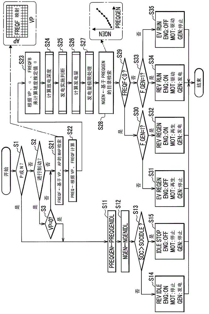
[0201] Next, the operation mode determination processing of the power unit PU of the second embodiment (refer to figure 2 )Be explained. The control device 30 of the power unit PU of the first embodiment and the second embodiment figure 2 In step S27 of, limit processing (power generation limit processing) is performed on the generator power generation output PREQGEN calculated in step S26. Here, the power generation limit processing of the first embodiment is Image 6 "Power generation limit processing (upper limit value)" shown. In contrast, the power generation limit processing of the second embodiment is Picture 9 The "power generation amount limit processing (lower limit value)" shown is different in this point. The rest is the same, so the description is omitted.
[0202]
[0203] Next, use Picture 9 The power generation limit processing (lower limit value) in step S27 will be described. Picture 9 It is a flowchart of the power generation amount limit processing (lower limit value) of the second embodiment.
[0204] In step S401, the control device 30 sets the power consumption PWRACHTR (PWRACHTR←power consumption by the air conditioner) consumed by the air conditioner. Here, the power consumption PWRACHTR consumed by the air conditioner is "0" when there is no currently used air conditioner (electric compressor 18, electric heater 19), and when there is currently used air conditioner (electric compressor 18, electric heater 19) is the maximum power consumption of the air conditioner (in the case of more than one, it is the total). Alternatively, the power consumption of the air conditioner (electric compressor 18, electric heater 19) may be estimated and obtained. For example, when the electric compressor 18 operates the refrigeration cycle to air-condition the vehicle interior, it is possible to estimate the power consumption based on the indoor temperature, the outdoor temperature, and the set temperature. In addition, when heating the vehicle interior by the electric heater 19, it is possible to estimate the power consumption based on the indoor temperature and the set temperature.
[0205] In step S402, the control device 30 is based on the vehicle speed VP and the road gradient estimated value θ (refer to figure 2 Step S23) to perform a mapping search (PGENLMTSLPL←MAP search based on VP and θ) for the lower limit value PGENLMTSLPL of the required power generation power of the vehicle speed and the gradient. It should be noted that the mapping of the vehicle speed and the gradient of the generated power required lower limit PGENLMTSLPL with respect to the vehicle speed VP and the gradient estimated value θ is stored in the control device 30 in advance. In addition, the mapping of the lower limit value PGENLMTSLPL of the vehicle speed and the gradient of the required power generation can be set such that as the estimated gradient value θ increases, the lower limit value PGENLMTSLPL of the generation power requirement increases, and as the vehicle speed VP increases, the generation power requirement The lower limit value PGENLMTSLPL becomes larger.
[0206] In step S403, the control device 30 performs a mapping search for the air conditioner and the surplus power generation power request lower limit PGENLMTSOCL based on the air conditioning power consumption PWRACHTR (refer to S401) and the remaining power SOC of the battery 11 (PGENLMTSOCL←based on PWRACHTR, SOC MAP retrieval). It should be noted that a map of the air-conditioning and surplus power demand lower limit PGENLMTSOCL with respect to the air-conditioning power consumption PWRACHTR and surplus power SOC is stored in the control device 30 in advance. In addition, the mapping between the air conditioner and the surplus power required lower limit PGENLMTSOCL can be set, for example, as the power consumption PWRACHTR consumed by the air conditioner increases, the generated power lower limit PGENLMTSOCL increases, and as the surplus power SOC increases , The lower limit PGENLMTSOCL of power generation requirement becomes larger.
[0207] In step S404, the control device 30 determines whether the lower limit value PGENLMTSLPL (refer to S402) of the vehicle speed and gradient required power generation is greater than the lower limit value PGENLMTSOCL (refer to S403) (PGENLMTSLPL>PGENLMTSOCL?) When the lower limit value PGENLMTSLPL of the vehicle speed and gradient required power generation is greater than the lower limit value PGENLMTSOCL of the air-conditioning and surplus electric power required (Yes in S404), the processing of the control device 30 proceeds to step S405. On the other hand, when the lower limit value PGENLMTSLPL of the vehicle speed and the gradient required power generation PGENLMTSLPL is not greater than the lower limit value PGENLMTSOCL of the air conditioner and remaining power generation power requirement (No in S404), the processing of the control device 30 proceeds to step S406.
[0208] In step S405, the control device 30 sets the first generated power limit value PGENLMTACHTRL to the generated power required lower limit value PGENLMTSLPL for vehicle speed and gradient (see S402) (PGENLMTACHTRL←PGENLMTSLPL). Then, the processing of the control device 30 proceeds to step S407.
[0209] In step S406, the control device 30 sets the first generation power limit value PGENLMTACHTRL to the air conditioning and surplus power generation power request lower limit value PGENLMTSOCL (see S403) (PGENLMTACHTRL←PGENLMTSOCL). Then, the processing of the control device 30 proceeds to step S407.
[0210] In step S407, the control device 30 inputs and sets the power consumption PWRDEV consumed by the auxiliary machine (PWRDEV←power consumption consumed by the auxiliary machine). Here, the power consumption PWRDEV consumed by the auxiliary machine is "0" when there is no auxiliary machine currently in use, and when there is an auxiliary machine currently in use, it is the maximum power consumption of the auxiliary machine (in the case of multiple). It should be noted that, here, the auxiliary equipment refers to equipment other than the air conditioner (electric compressor 18, electric heater 19) and electric motor 14 that consumes electric power from the battery 11 and operates.
[0211] In step S408, the control device 30 performs a mapping search for the second generation power limit value PGENLMTDEVL based on the power consumption PWRDEV (refer to S407) consumed by the auxiliary machinery and the remaining power SOC of the battery 11 (PGENLMTDEVL←MAP search based on PWRDEV and SOC) . It should be noted that the mapping of the second power generation limit value PGENLMTDEVL with respect to the power consumption PWRDEV consumed by the auxiliary machine and the remaining power SOC is stored in the control device 30 in advance. In addition, the mapping of the second power generation limit value PGENLMTDEVL can be set such that as the power consumption PWRDEV consumed by the auxiliary machinery increases, the second generation power limit value PGENLMTDEVL increases, and as the remaining power SOC increases, the second power generation The power limit value PGENLMTDEVL becomes larger.
[0212] In step S409, control device 30 sets the final generated power limit value PWRGENLMTL to the sum of the first generated power limit value PGENLMTACHTRL (see S405, S406) and the second generated power limit value PGENLMTDEVL (see S409) ( PWRGENLMTL←PGENLMTACHTRL+PGENLMTDEVL).
[0213] In step S410, the control device 30 determines the generator power generation output PREQGEN (refer to Figure 5 S308, S309) is greater than the final power generation limit value PWRGENLMTL (refer to S409) (PREQGEN>PWRGENLMTL?). When the generator power generation output PREQGEN is greater than the final power generation limit value PWRGENLMTL (Yes in S410), the processing of the control device 30 proceeds to step S411. On the other hand, in the case where the generator power generation output PREQGEN is not greater than the final power generation limit value PWRGENLMTL (NO in S410), the processing of the control device 30 proceeds to step S412.
[0214] In step S411, the control device 30 sets the generator power generation output PREQGEN to the generator power generation output PREQGEN (PREQGEN←PREQGEN). Then, the power generation limit processing (step S27) is ended, and the process proceeds to step S28 (refer to figure 2 ).
[0215] In step S412, the control device 30 sets the generator power generation output PREQGEN to the final power generation limit value PWRGENLMTL (PREQGEN←PWRGENLMTL). Then, the power generation limit processing (step S27) is ended, and the process proceeds to step S28 (refer to figure 2 ).
[0216] Here, use Picture 10 , Explain the function and effect of power generation limit treatment. Picture 10 It is a graph explaining the power generation limit processing (lower limit value) of the second embodiment, (a) is a graph showing the relationship between the actual fuel consumption rate (BSFC) and the output of the internal combustion engine, (b) is the power output A graph of the relationship with vehicle speed. It should be noted, Picture 10 In (b), the power generation output (generator power generation output PREQGEN) of the auxiliary power section S of each remaining power SOC before the limit processing is represented by a solid line (when not limited), and the required power of the electric motor 14 relative to the vehicle speed VP (Required drive output PREQ) is represented by a one-dot chain line (M).
[0217] The power consumption of the air conditioner (electric compressor 18) and the heater (electric heater 19) of the air conditioner does not depend on the driving conditions (for example, vehicle speed VP), and the power consumption increases when the operation of the air conditioner starts. Therefore, if the operation of the air conditioner is started at a low vehicle speed, in the case of the so-called "cruise output following type control" in which the power generation amount is changed according to the vehicle speed VP, the remaining power SOC of the battery 11 is drastically reduced, and the energy balance is The balance may be disrupted. In addition, if the continuous high-load operation (for example, traveling on an uphill road) is performed in a state where the remaining power SOC of the battery 11 is reduced, in the case of a configuration with a low-power generator 16 (an internal combustion engine 15 with a small displacement) , May not meet the output requirements of the motor 14.
[0218] On the other hand, according to the present embodiment, the larger of the lower limit value PGENLMTSLPL (refer to S402) and the lower limit value PGENLMTSOCL (refer to S403) for generating power required for air conditioning and surplus power is set as the first A generation power limit value PGENLMTACHTRL (refer to S405, S406), and also consider the second generation power limit value PGENLMTDEVL (refer to S408) based on the power consumption PWRDEV consumed by the auxiliary machinery and the remaining power SOC to perform the limit processing of the lower limit (refer to S409, S410).
[0219] Such as Picture 10 As shown in (b), the power generation output at the limit indicated by the dotted line ( figure 2 The generator power generation output PREQGEN processed in step S27 in step S27 becomes the power generation output ( figure 2 The generator output PREQGEN obtained in step S26 of the above) and the lower limit value ( Picture 9 The final generated power limit value (PWRGENLMTL) of step S409 is high.
[0220] Therefore, even if it is a structure provided with the low-output generator 16 (the internal combustion engine 15 with a small displacement), it can become a robust system with respect to the sudden change of a running load, and can maintain an energy balance.
[0221] In addition, such as Picture 10 As shown in (b), in the medium and high vehicle speed regions, the power generation output during restriction is the same as the power generation output during non-restriction. In this way, when the energy balance is established by the normal basic cruise output power generation during continuous downhill or when the power storage state is greater than the equilibrium state, etc., the output restriction is immediately released, so it is possible to prevent the fuel utilization rate caused by excessive power generation. deterioration.

Example

[0222] "Third Implementation Mode"
[0223]
[0224] Next, the power unit PU of the third embodiment will be described. The overall structure of the power unit PU of the third embodiment is the same as the power unit PU of the first embodiment (refer to figure 1 ) Are the same, so the description is omitted.
[0225]
[0226] Next, use Picture 11 The operation mode determination processing of the power unit PU of the third embodiment will be described. Picture 11 It is a flowchart of the operation mode determination processing of the power unit PU of the third embodiment.
[0227] Operation mode determination processing of the first embodiment (refer to figure 2 ) Calculate the amount of power generated by the generator 16, that is, the generator output PREQGEN (see step S26), and limit the generator output PREQGEN (see step S27), and then obtain the rotational speed of the internal combustion engine 15, that is, the generator The engine rotation speed NGEN (refer to step S28).
[0228] In contrast, the operation mode determination processing of the third embodiment (refer to Picture 11 ) Calculate the rotation speed of the internal combustion engine 15, that is, the engine rotation speed NGEN for generators (refer to step S26A), and limit the engine rotation speed NGEN for generators (refer to step S27A), to obtain the power generation amount of the generator 16, namely The generator output PREQGEN (refer to step S28A) is different in this point. Other processing (steps S1 to 3, S11 to 115, S21 to 25, S29 to S35) and the operation mode determination processing of the first embodiment (refer to figure 2 ) Are the same, so the description is omitted.
[0229] In step S26A, the control device 30 calculates (rotation speed calculation) the rotation speed of the internal combustion engine 15, that is, the rotation speed NGEN of the engine for generator. use Picture 12 The details will be described later.
[0230] In step S27A, the control device 30 performs limit processing (rotation speed limit processing) on ​​the engine rotation speed NGEN for the generator calculated in step S26A. use Figure 13 The details will be described later.
[0231] In step S28A, the control device 30 performs a catalog search on the power generation amount of the generator 16, that is, the generator power output PREQGEN based on the generator internal combustion engine rotation speed NGEN after the limit processing in step S27A (PREQGEN←NGEN-based catalog search ). It should be noted that a list of the generator power generation output PREQGEN with respect to the engine rotation speed NGEN for the generator is stored in the control device 30 in advance. In addition, such as Picture 11 As shown, in this catalog, as the engine rotation speed NGEN for generators increases, the generator output PREQGEN increases.
[0232]
[0233] Next, use Picture 12 The rotation speed calculation processing in step S26A will be described. Picture 12 It is a flowchart of the rotation speed calculation process of the third embodiment.
[0234] In step S301A, based on the vehicle speed VP, the control device 30 performs a catalog search (NGENRL← catalog search based on VP) for the generator internal combustion engine basic rotation speed NGENRL corresponding to the output required for cruising at each vehicle speed. Here, the basic rotational speed NGENRL of the internal combustion engine for generators, which is equivalent to the output required for cruising at each vehicle speed, is the one that can obtain the internal combustion engine 15 that enables the electric motor 14 to generate electric power that overcomes only the air resistance Ra and rolling resistance Rr of the vehicle. spinning speed. It should be noted that a list of the basic rotational speed NGENRL of the internal combustion engine for generators with respect to the vehicle speed VP corresponding to the output required for cruising at each vehicle speed is stored in the control device 30 in advance. In addition, such as Picture 12 As shown, in this catalog, as the vehicle speed VP increases, the basic rotation speed NGENRL of the internal combustion engine for a generator, which is equivalent to the output required for cruising at each vehicle speed, increases.
[0235] In step S302A, control device 30 estimates value θ based on vehicle speed VP and the gradient of the road surface (refer to Picture 11 Step S23) to perform a map search (DNGENSLP←MAP search based on VP and θ) for the power generation rotation speed correction amount DNGENSLP for each vehicle speed and gradient. It should be noted that the mapping of the power generation rotation speed correction amount DNGENSLP for each vehicle speed and gradient with respect to the vehicle speed VP and the gradient estimated value θ is stored in the control device 30 in advance. In addition, the mapping of the power generation rotation speed correction amount DNGENSLP for each vehicle speed and the gradient can be set such that as the estimated slope value θ becomes larger, the power generation rotation speed correction amount DNGENSLP becomes larger, and when the estimated slope value θ is constant, As the vehicle speed VP increases, the power generation rotation speed correction amount DNGENSLP decreases.
[0236] In step S303A, the control device 30 performs a catalog search based on the vehicle speed VP by adding the basic amount DNGENBASE to the power generation rotation speed at each vehicle speed (DNGENBASE ← catalog search based on VP). It should be noted that a list of the additional basic amount DNGENBASE of the power generation rotation speed at each vehicle speed relative to the vehicle speed VP is stored in the control device 30 in advance. In addition, such as Picture 12 As shown, in this catalog, as the vehicle speed VP increases, the additional basic amount DNGENBASE of the power generation rotation speed at each vehicle speed decreases.
[0237] In step S304A, the control device 30 performs a map search (DNGENDOD←MAP search based on VP and DOD) for the additional amount of power generation rotation speed DNGENDOD for each vehicle speed and depth of discharge based on the vehicle speed VP and the depth of discharge DOD. It should be noted that the mapping of the power generation rotation speed addition amount DNGENDOD for each vehicle speed and the depth of discharge to the vehicle speed VP and the depth of discharge DOD is stored in the control device 30 in advance. In addition, the mapping of the additional amount of power generation rotation speed DNGENDOD for each vehicle speed and the depth of discharge can be set such that as the depth of discharge DOD increases, the additional amount of power generation rotation speed DNGENDOD increases, and when the depth of discharge DOD is constant, As the vehicle speed VP increases, the additional amount of power generation rotation speed DNGENDOD decreases.
[0238] In step S305A, the control device 30 performs a map search (DNGENSOC ← MAP search based on VP and SOC) for each vehicle speed and the power generation rotation speed addition amount DNGENSOC for each vehicle speed and the remaining power based on the vehicle speed VP and the remaining power SOC. It should be noted that a map of the additional amount of power generation rotation speed DNGENSOC for each vehicle speed and the remaining power with respect to the vehicle speed VP and the remaining power SOC is stored in the control device 30 in advance. In addition, the mapping between each vehicle speed and the additional amount of power generation rotation speed DNGENSOC can be set such that as the remaining power SOC decreases, the additional power generation rotation speed DNGENSOC increases, and when the remaining power SOC is constant, As the vehicle speed VP increases, the additional amount of power generation rotation speed DNGENSOC decreases.
[0239] In step S306A, based on the vehicle speed VP, the control device 30 performs a directory search (DNGENAC←directory search based on VP) for the additional amount DNGENAC of the power generation rotation speed when the air conditioner is used for each vehicle speed. It should be noted that a list of the additional amount of power generation rotation speed DNGENAC at the time of air conditioning use for each vehicle speed relative to the vehicle speed VP is stored in the control device 30 in advance. In addition, such as Picture 12 As shown, in this list, as the vehicle speed VP increases, the additional amount of power generation rotation speed DNGENAC during air conditioning use at each vehicle speed decreases.
[0240] In step S307A, the control device 30 determines whether the air-conditioning use flag F_AC is "1" (air-conditioning is used) (F_AC=1?). It should be noted that when the electric compressor 18 and/or the electric heater 19 are operating, the air-conditioning ECU 36 sets the air-conditioning use flag F_AC to "1" (air conditioning is used), and does not operate the electric compressor 18 and the electric heater 19 When the air conditioner use flag F_AC is "0" (no air conditioner is used). When the air-conditioning use flag F_AC is "1" (air-conditioning is used) (Yes in S307A), the processing of the control device 30 proceeds to step S309A. On the other hand, when the air-conditioning use flag F_AC is not "1" (air-conditioning is used) (NO in S307A), the processing of the control device 30 proceeds to step S308A.
[0241] In step S308A, the control device 30 sets the rotation speed of the internal combustion engine 15, that is, the generator engine rotation speed NGEN to the generator engine basic rotation speed NGENRL (refer to S301A) corresponding to the output required for cruise at each vehicle speed, each The power generation rotation speed correction amount for vehicle speed and gradient DNGENSLP (refer to S302A), the basic power generation rotation speed addition amount DNGENBASE (refer to S303A) for each vehicle speed, the power generation rotation speed addition amount DNGENDOD (refer to S304A) for each vehicle speed and depth of discharge, and each vehicle speed The value added to the surplus power generation rotation speed addition amount DNGENSOC (see S305A). Then, the rotation speed calculation process is ended (step S26A), and the process proceeds to step S27A (refer to Picture 11 ).
[0242] In step S309A, the control device 30 sets the rotation speed of the internal combustion engine 15, that is, the generator engine rotation speed NGEN to the generator engine basic rotation speed NGENRL (refer to S301A) corresponding to the output required for cruise at each vehicle speed. The power generation rotation speed correction amount for vehicle speed and gradient DNGENSLP (refer to S302A), the power generation rotation speed addition base amount DNGENBASE (refer to S303A) at each vehicle speed, the power generation rotation speed addition amount for each vehicle speed and depth of discharge DNGENDOD (refer to S304A), each vehicle speed The value added to the power generation rotation speed addition amount DNGENSOC (see S305A) of the remaining power and the power generation rotation speed addition amount DNGENAC (see S306A) when the air conditioner is used for each vehicle speed. Then, the rotation speed calculation process is ended (step S26A), and the process proceeds to step S27A (refer to Picture 11 ).
[0243]
[0244] Next, use Figure 13 The rotation speed limit processing (upper limit value) in step S27A will be described. Figure 13 It is a flowchart of the rotation speed limit process (upper limit value) of the third embodiment.
[0245] In step S501A, the control device 30 performs a catalog search for the upper limit output equivalent rotation speed NUMSOC of the BSFC optimal region based on the remaining power SOC of the battery 11 (NUMSOC← catalog search based on SOC). It should be noted that a list of the upper limit output equivalent of the BSFC optimal area rotation speed NUMSOC relative to the remaining power SOC is stored in the control device 30 in advance. In addition, such as Figure 13 As shown, in this catalog, as the remaining power SOC becomes larger, the upper limit output of the BSFC optimal region corresponds to the rotation speed NUMSOC becomes larger.
[0246] In step S502A, control device 30 estimates value θ based on vehicle speed VP and the gradient of the road surface (see Picture 11 Step S23) to perform a mapping search (NGENLMTSLP ← MAP search based on VP and θ) for the vehicle speed and the gradient of the power generation rotation speed request upper limit NGENLMTSLP. It should be noted that the mapping of the vehicle speed and the gradient of the power generation rotation speed request upper limit NGENLMTSLP with respect to the vehicle speed VP and the gradient estimated value θ is stored in the control device 30 in advance. In addition, the mapping of the power generation rotation speed requirement upper limit NGENLMTSLP of vehicle speed and gradient can be set such that as the estimated gradient value θ becomes larger, the power generation rotation speed requirement upper limit NGENLMTSLP becomes larger, and as the vehicle speed VP becomes larger, the power generation The rotation speed request upper limit NGENLMTSLP becomes larger.
[0247] In step S503A, the control device 30 inputs and sets the rotation speed NUMACHTR equivalent to the power consumption of the air conditioner (NUMACHTR←The power consumption equivalent to the rotation speed of the air conditioner). Here, the power consumption equivalent to the rotation speed NUMACHTR of the air conditioner is "0" when there is no currently used air conditioner (electric compressor 18, electric heater 19), and when the currently used air conditioner (electric compressor 18, The electric heater 19) is the rotation speed of the internal combustion engine 15 that can obtain the maximum power consumption of the air-conditioning apparatus (in the case of more than one, it is the total). Alternatively, the power consumption of the air conditioner (electric compressor 18, electric heater 19) may be estimated to obtain the rotation speed of the internal combustion engine 15 that can obtain the power consumption.
[0248] In step S504A, the control device 30 sets the power generation rotation speed request upper limit NUMLMT determined by the air conditioner and the gradient to the power generation rotation speed request upper limit NGENLMTSLP (refer to S502A) of the vehicle speed and the gradient and the power consumption of the air conditioner is equivalent to rotation Speed ​​NUMACHTR (refer to S503A) added value (NUMLMT←NGENLMTSLP+NUMACHTR).
[0249] In step S505A, the control device 30 determines whether the power generation rotation speed required upper limit NUMLMT (refer to S504A) determined by the air conditioner and the gradient is greater than the upper limit output equivalent rotation speed NUMSOC (refer to S501A) (NUMLMT>NUMSOC?) . When the power generation rotation speed required upper limit NUMLMT determined by the air conditioner and the gradient is greater than the upper limit output equivalent rotation speed NUMSOC of the BSFC optimum area (Yes in S505A), the processing of the control device 30 proceeds to step S506A. On the other hand, if the required upper limit NUMLMT of the power generation rotation speed determined by the air conditioner and the gradient is not greater than the upper limit output equivalent rotation speed NUMSOC of the BSFC optimum area (S505A: No), the processing of the control device 30 proceeds to step S507A .
[0250] In step S506A, the control device 30 sets the final power generation rotation speed limit value NUMGENLMT to the power generation rotation speed request upper limit NUMLMT (refer to S504A) (NUMGENLMT←NUMLMT) determined by the air conditioner and the gradient. Then, the processing of the control device 30 proceeds to step S508A.
[0251] In step S507A, the control device 30 sets the final power generation rotation speed limit value NUMGENLMT as the upper limit output equivalent rotation speed NUMSOC of the BSFC optimum region (refer to S501A) (NUMGENLMT←NUMSOC). Then, the processing of the control device 30 proceeds to step S508A.
[0252] In step S508A, the control device 30 determines the engine rotation speed NGEN for the generator (refer to Picture 12 S308A, S309A) is greater than the final power generation rotation speed limit value NUMGENLMT (refer to S506A, S507A) (NGEN>NUMGENLMT?). When the engine rotation speed NGEN for generator is greater than the final power generation rotation speed limit value NUMGENLMT (Yes in S508A), the processing of the control device 30 proceeds to step S509A. On the other hand, in the case where the engine rotation speed NGEN for the generator is not greater than the final power generation rotation speed limit value NUMGENLMT (NO in S508A), the processing of the control device 30 proceeds to step S510A.
[0253] In step S509A, the control device 30 sets the engine rotation speed NGEN for the generator to the final power generation rotation speed limit value NUMGENLMT (NGEN←NUMGENLMT). Then, the rotation speed limit processing (step S27A) is ended, and the process proceeds to step S28A (refer to Picture 11 ).
[0254] In step S510A, the control device 30 sets the engine rotation speed NGEN for generator to the engine rotation speed NGEN for generator (NGEN←NGEN). Then, the rotation speed limit processing (step S27A) is ended, and the process proceeds to step S28A (refer to Picture 11 ).
[0255] In this way, in the processing of the power unit PU of the third embodiment, the same action and effect as the processing of the power unit PU of the first embodiment can be obtained.

PUM

no PUM

Description & Claims & Application Information

We can also present the details of the Description, Claims and Application information to help users get a comprehensive understanding of the technical details of the patent, such as background art, summary of invention, brief description of drawings, description of embodiments, and other original content. On the other hand, users can also determine the specific scope of protection of the technology through the list of claims; as well as understand the changes in the life cycle of the technology with the presentation of the patent timeline. Login to view more.

Similar technology patents

Statistical method and device for user behavior data

Owner:WUHAN DOUYU NETWORK TECH CO LTD

Hotel vehicle booking method and system

InactiveCN105095979AReduce user inputImprove operational efficiency
Owner:CHUANCHENG CULTURE & MEDIA SHANGHAI

Information processing method, electronic device and system

ActiveCN103986502AImprove operational efficiencyGuaranteed experience
Owner:LENOVO (BEIJING) CO LTD

Cross-industry data resource integration system based on big data

InactiveCN110147400AReduce logistics costsImprove operational efficiency
Owner:QI AUTOMOTIVE CO LTD

Frequency adjusting method and device of frozen water pump and air conditioning system

PendingCN108775661ASolve high energy consumptionImprove operational efficiency
Owner:GREE ELECTRIC APPLIANCES INC OF ZHUHAI

Classification and recommendation of technical efficacy words

  • Improve operational efficiency

Alarm association rule obtaining method of mobile internet

ActiveCN102098175AAccurate resultsImprove operational efficiency
Owner:INSPUR TIANYUAN COMM INFORMATION SYST CO LTD

Automatic robot, control device and control method

Owner:BEIJING XIAOMI MOBILE SOFTWARE CO LTD +1

Operation processing method and device

Owner:BUBI BEIJING NETWORK TECH CO LTD

Automatic guided vehicle (AGV) scheduling control system

InactiveCN109669456AImprove operating system efficiencyImprove operational efficiency
Owner:WUHU HIT ROBOT TECH RES INST
Why Eureka
Try Eureka