
Universal bottle stopper

A bottle stopper and outer shell technology, applied in the direction of expandable sealing parts, etc., can solve problems such as affecting the quality of the objects in the bottle, difficult to ensure the sealing effect of the bottle mouth, and loss of sealing.

Active Publication Date: 2015-06-17
淮安市清江浦区市场监管综合服务中心
View PDF7 Cites 0 Cited by
  • Summary
  • Abstract
  • Description
  • Claims
  • Application Information

AI Technical Summary

Problems solved by technology

In order to obtain a better sealing performance for the bottle mouth, someone invented an expansion-type bottle stopper (Notice No. 101372274). A moving member, the body member can be used for the first section of longitudinal movement, the elastic member is longitudinally expanded, so that it is firmly attached to the inner wall of the container opening, and the body member can be used for the second The longitudinal movement of the section makes the elastic member shrink radially so that the bottle stopper can be easily taken out from the opening of the container. Although this kind of bottle stopper has a good cork function, it can only be used for Containers of one specification and caliber are used together and have the characteristics of one-time use
When the substance in the bottle needs to be kept for next use in daily life, or the empty bottle is used for secondary use, because the bottle stopper is for one-time use, the seal of the bottle mouth loses the original matching bottle stopper, and it is necessary to find Other bottle stoppers can be used instead, but other stoppers may not just fit the bottle mouth, so it is difficult to ensure that the bottle mouth achieves a good sealing effect, which affects the quality of the objects in the bottle

Method used

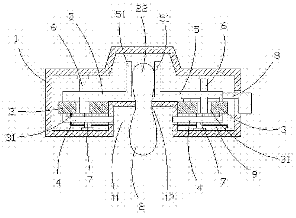
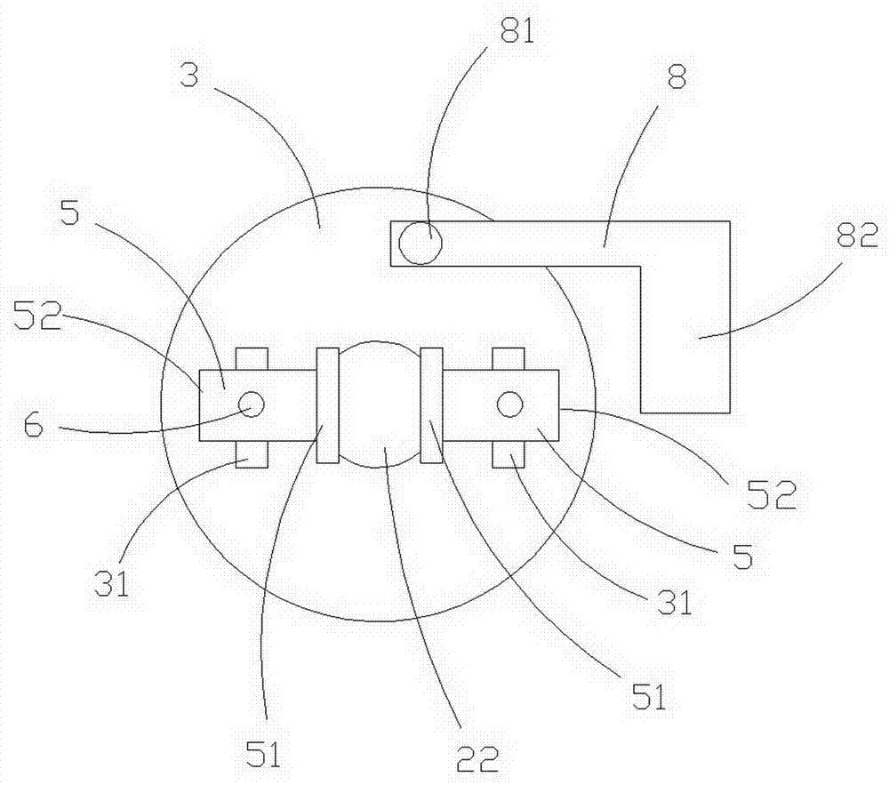
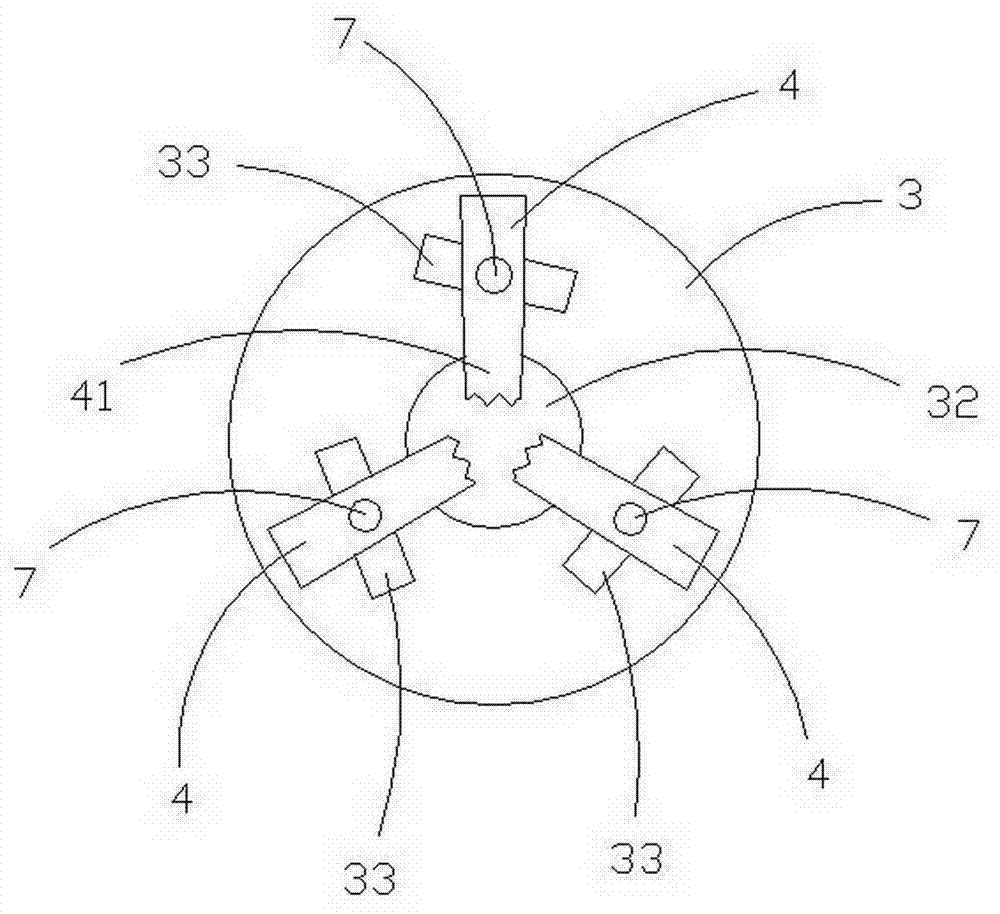

Image

  • Universal bottle stopper
  • Universal bottle stopper
  • Universal bottle stopper

Examples


Embodiment Construction

[0015] Such as figure 1 , 2 As shown in , 3, a kind of universal bottle stopper, comprises outer shell 1, is provided with an inwardly recessed bottleneck accommodating groove 11 in the center of the lower end face of outer shell 1, is equipped with punching hole 12 in the through hole 12 of accommodating groove bottom. The air bag 2, the air bag is strip-shaped. The bottle stopper 21 of the air bag 2 stretches out of the housing groove 11, the air pressure portion 22 of the air bag is located in the inner cavity of the outer casing 1, and the air flow control parts 5 are arranged on both sides of the air pressure portion 22 of the air bag, and the drive plate 3 The central hole 32 is sleeved on the outer wall of the inwardly protruding accommodation groove 11, the airflow control part 5 is located above the driving disk 3, the clamping part 52 of the airflow control part is interlocked in the slot of the driving disk 3, and the positioning guide pin I6 The airflow control p...


PUM


Abstract

The invention discloses a general bottle stopper. An internally concave bottle mouth accommodation groove is formed in the lower end surface of a casing of the bottle stopper, a bottle stopper part of an external aerated air bag and an air pressing part of an internal aerated air bag are arranged in a through hole in the bottom part of the accommodation groove, an air flow control piece is arranged on each of two sides of the air pressing part of the aerated air bag, a positioning guide pin I penetrates through and is connected with the air flow control pieces and then the top end of the positioning guide pin is left in a guiding hole of a driving plate, a clamping connection part of each air flow control piece is clamped in a clamping groove of the driving plate, three clamping claws connected through a positioning guide pin II in a penetrating way are arranged on the lower end surface of the driving plate, one end of each clamping claw is in clamped connection with the driving plate and the other locking end of the clamping claw is telescopically arranged in a guiding-out hole formed in the side wall of the accommodation groove, two ends of an elastic ring are fixedly connected to the driving plate and a connecting seat, a push rod drives the driving plate to rotate so that the clamping claws lock the bottle mouth, and simultaneously the air flow control pieces push the air pressing part of the aerated air bag to unequally and radially expand the volume of the bottle plug part of the aerated air bag in the bottle mouth, and therefore the bottle mouth is tightly plugged and sealed.

Description

technical field [0001] The invention relates to a bottle stopper, in particular to a universal bottle stopper. Background technique [0002] Bottles and cans are widely used in daily life. These containers cannot be sealed without a cork. The structure and quality of the cork are related to whether the contents in the container can be preserved for a long time. In order to obtain a better sealing performance for the bottle mouth, someone invented an expansion-type bottle stopper (Notice No. 101372274). A moving member, the body member can be used for the first section of longitudinal movement, the elastic member is longitudinally expanded, so that it is firmly attached to the inner wall of the container opening, and the body member can be used for the second The longitudinal movement of the section makes the elastic member shrink radially so that the bottle stopper can be easily taken out from the opening of the container. Although this kind of bottle stopper has a good cor...

Claims


Application Information

Patent Timeline
Patent Type & Authority Applications(China)
IPC IPC(8): B65D39/12
Inventor 蒋祥初
Owner 淮安市清江浦区市场监管综合服务中心
Learn More