
Foam component and its processing method

A processing method and foam technology, applied in metal processing, adhesives, film/sheet-like adhesives, etc., can solve the problems of residue left in the inner frame, high displacement and deformation of the frame, and large waste discharge in the inner frame. Achieve the effects of convenient punching and cutting, reducing the risk of displacement and deformation

Active Publication Date: 2017-03-15
BYD CO LTD
View PDF1 Cites 0 Cited by
  • Summary
  • Abstract
  • Description
  • Claims
  • Application Information

AI Technical Summary

Problems solved by technology

[0003] At this time, since the bottom surface of the foam is supported as a whole, under the same support force, if the support force of the frame is guaranteed, the waste discharge of the inner frame will require a greater force, which will easily cause the foam to tear and leave residue on the inner frame
If it is to ensure that the waste of the inner frame is easy to discharge, it is easy to drive the frame, causing displacement and deformation
[0004] At the same time, in the case of strong supporting force, most of them use manual waste discharge, which is very inefficient
In the case of weak supporting force, equipment waste can be discharged, but the probability of frame displacement and deformation is high

Method used

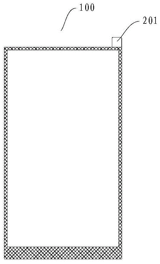
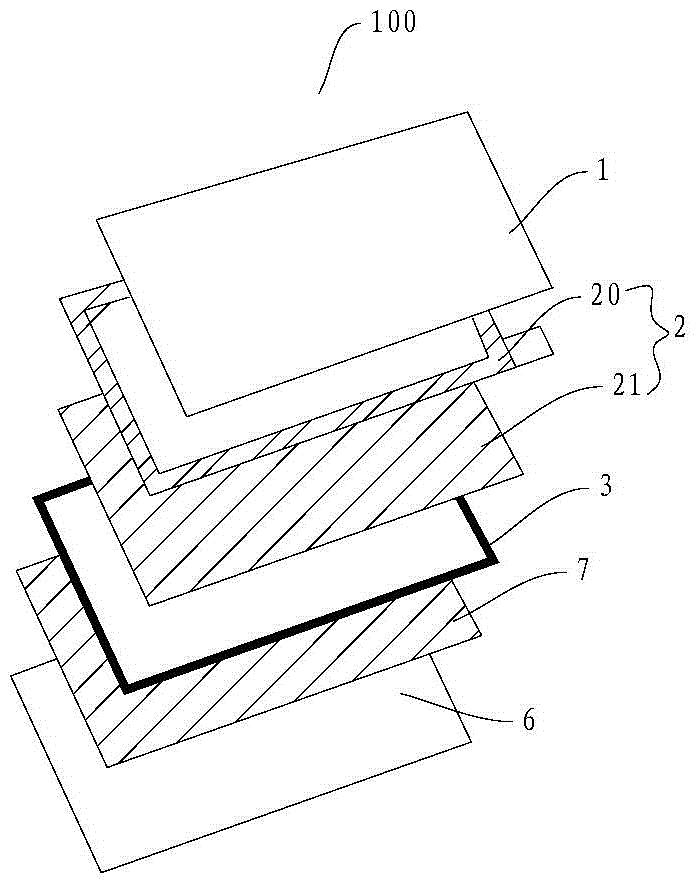

Image

  • Foam component and its processing method
  • Foam component and its processing method
  • Foam component and its processing method

Examples


Embodiment Construction

[0018] Embodiments of the present invention are described in detail below, examples of which are shown in the drawings, wherein the same or similar reference numerals designate the same or similar elements or elements having the same or similar functions throughout. The embodiments described below by referring to the figures are exemplary and are intended to explain the present invention and should not be construed as limiting the present invention.

[0019] In describing the present invention, it should be understood that the terms "center", "longitudinal", "transverse", "length", "width", "thickness", "upper", "lower", "front", " Orientation or position indicated by "back", "left", "right", "vertical", "horizontal", "top", "bottom", "inner", "outer", "clockwise", "counterclockwise", etc. The relationship is based on the orientation or positional relationship shown in the drawings, and is only for the convenience of describing the present invention and simplifying the descrip...


PUM


Abstract

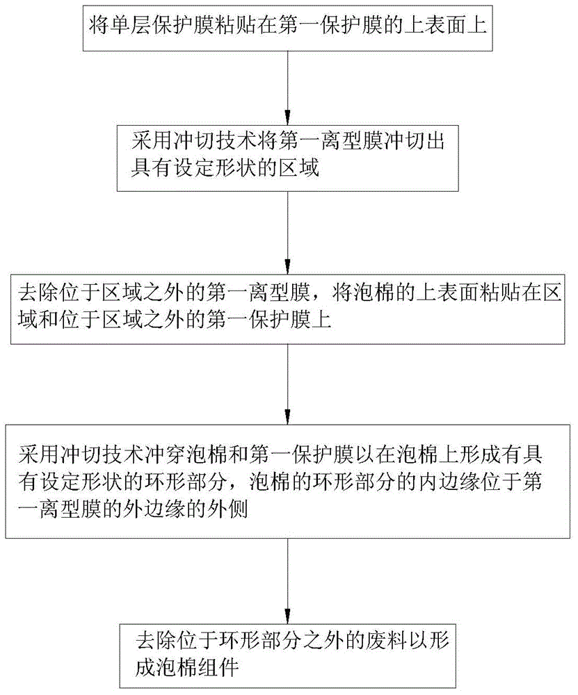
The invention discloses a foam component and a processing method thereof. The processing method includes the steps of: S1: sticking a monolayer protective film to the upper surface of a first protective film; S2: punching an area with a set shape on a release film by a punching technology; S3: removing a first release film located outside the area, and sticking the upper surface of the foam on the first protective film in the area and beyond the area; S4: punching the foam and the first protective film through by a punching technology to form an annular part on the foam, with the inner edge of the foam's annular part located outside the outer edge of the first release film; and S5: removing the water material outside the annular part. The processing method for the foam component provided by the invention facilitates the punching processing of foam and reduces the shift deformation risk of the foam frame.

Description

technical field [0001] The invention relates to the field of precision die cutting, in particular to a foam component and a processing method thereof. Background technique [0002] In the die-cutting production process, foam is a common material used, but due to the characteristics of the foam itself, the frame of the back-shaped foam is relatively narrow, and it is more difficult to process. Because the foam is easy to deform, it will be displaced and deformed by the extrusion of the die during punching. At this time, it is necessary to add a layer of material on the bottom of the foam to support the foam frame. [0003] At this time, because the bottom surface of the foam is supported as a whole, under the same support force, if the support force of the frame is guaranteed, the waste discharge of the inner frame will require a greater force, which will easily cause the foam to tear and leave residues in the inner frame . If it is to ensure that the inner frame waste is e...

Claims


Application Information

Patent Timeline
Patent Type & Authority Patents(China)
IPC IPC(8): B26F1/38C09J7/02
Inventor 徐磊
Owner BYD CO LTD
Learn More