Method for measuring diffraction loss of laser gyro

A technology of diffraction loss and measurement method, which is applied in the direction of measuring devices, instruments, etc., can solve the problem of precise measurement of laser gyro diffraction loss, etc., and achieve the effect of great practical application value, high measurement accuracy and repeatability, and short operation cycle

Inactive Publication Date: 2015-06-17
FLIGHT AUTOMATIC CONTROL RES INST
View PDF6 Cites 6 Cited by
  • Summary
  • Abstract
  • Description
  • Claims
  • Application Information

AI Technical Summary

Problems solved by technology

[0004] In order to solve the problem that it is difficult to accurately measure the laser gyro diffraction loss in the prior art, the present invention provides a method that can realize the precise loss measurement of the laser gyro diffraction loss

Method used


Image

  • Method for measuring diffraction loss of laser gyro
  • Method for measuring diffraction loss of laser gyro
  • Method for measuring diffraction loss of laser gyro

Examples


Embodiment Construction

[0030] The present invention will be further described through specific implementations below:

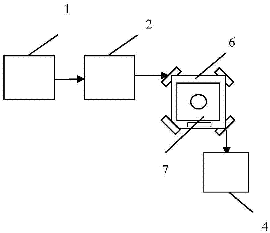
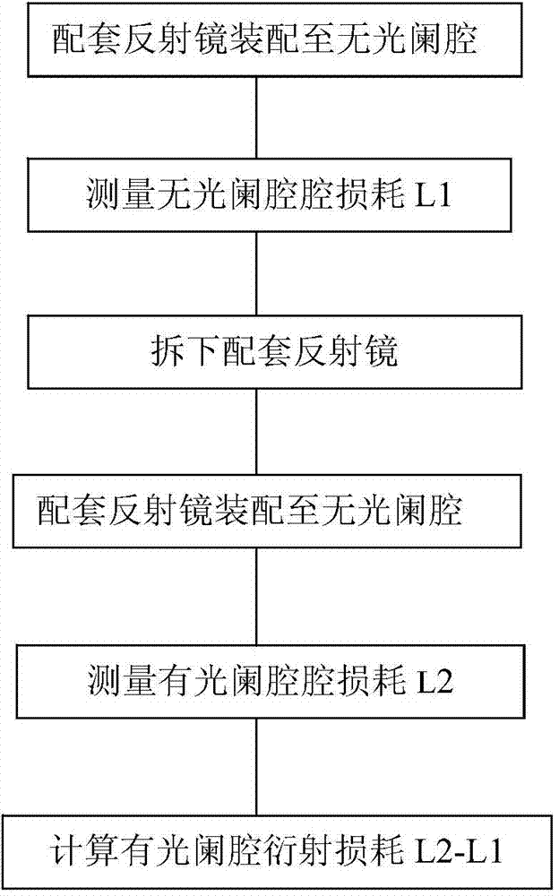
[0031] The method for measuring the diffraction loss of the laser gyro of the present invention is by assembling the matching mirrors on the cavity with and without the diaphragm respectively, and measuring the cavity loss in the resonant cavity composed of the cavity with or without the diaphragm and the matching mirror by the time attenuation method. , And then subtracted to get the diffraction loss of the diaphragm cavity.

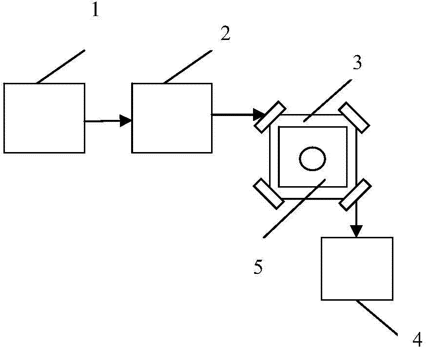
[0032] See figure 1 , Which is a schematic diagram of the connection diagram for the measurement method of the diffraction loss of the laser gyro of the present invention without the diaphragm resonator loss. In the figure, the swept laser 1 adjusts the optical path matching component 2 to inject the laser output from the swept laser into the non-aperture resonant cavity 5, and the loss measurement and control system 4 measures the cavity loss L1 of the non-aper...


PUM


Abstract

The invention belongs to a method for measuring the loss parameter of a laser gyro, and relates to a method for measuring the diffraction loss of the laser gyro. The measurement method comprises the following steps: assembling a matched reflector to an unapertured cavity, starting a frequency sweep laser, adjusting a light path matching part to make laser enter a resonant cavity composed of an unapertured diaphragm and the reflector, and measuring the initial cavity loss L1 of the unapertured diaphragm resonant cavity through a loss measurement system; disassembling the matched reflector from the unapertured resonant cavity [5], assembling the matched reflector to an apertured cavity, adjusting the light path matching part to make the laser enter a resonant cavity composed of the apertured cavity and the reflector, and measuring the cavity loss L2 of the apertured diaphragm resonant cavity through the loss measurement system [4]; and calculating a difference between the cavity loss L2 and the cavity loss L1 to obtain the diffraction loss of the apertured diaphragm resonant cavity. The method has the advantages of strong operationality, small error and high measurement precision, solves a problem that the measuring diffraction loss of the laser gyro cannot be accurately measured in the prior art, and has good application values.

Description

Technical field [0001] The invention relates to a method for measuring the loss of a laser gyro, in particular to a method for measuring the diffraction loss of a laser gyro. Background technique [0002] The laser gyroscope is an inertial device that is sensitive to the rotation speed of the outside through the optical path difference in the forward and reverse directions in the cavity, and its work requires the fundamental mode state. In order to suppress the oscillation of the high-order mode in the cavity, an aperture is usually set at an appropriate position in the cavity, and the difference in diffraction loss of each transverse mode to the aperture is used to suppress the oscillation of the high-order mode to ensure the fundamental mode oscillation. Therefore, diffraction loss plays a vital role in laser gyro, but in order to ensure that the gyro works in the fundamental mode, the diffraction loss cannot be increased without limit, which will inevitably cause problems such...

Claims


Application Information

Patent Timeline
Patent Type & Authority Applications(China)
IPC IPC(8): G01C25/00
CPCG01C25/005
Inventor 王朋国张自国
Owner FLIGHT AUTOMATIC CONTROL RES INST
Why Eureka
Try Eureka