Thyristor breakover voltage drop measurement system and method

A technology of conduction voltage drop and measurement system, which is applied in the direction of measuring electrical variables, measuring devices, measuring current/voltage, etc., and can solve problems such as inaccurate measurement of thyristor conduction voltage drop and inability to accurately measure thyristor conduction voltage drop. , to achieve the effect of precise control and accurate measurement

Inactive Publication Date: 2015-06-17
HUAZHONG UNIV OF SCI & TECH
View PDF3 Cites 10 Cited by
  • Summary
  • Abstract
  • Description
  • Claims
  • Application Information

AI Technical Summary

Problems solved by technology

[0003] In the prior art, there is a problem of inaccurate measurement of the conduction voltage drop of the thyristor in the measurement of the junction temperature by the thermal parameter method
The current of the thyristor at the turn-on moment is close to zero, and the turn-on voltage drop is a small voltage value close to the threshold voltage; since the thyristor is in the blocki

Method used


Image

  • Thyristor breakover voltage drop measurement system and method
  • Thyristor breakover voltage drop measurement system and method
  • Thyristor breakover voltage drop measurement system and method

Examples


Embodiment Construction

[0035] In order to make the object, technical solution and advantages of the present invention clearer, the present invention will be further described in detail below in conjunction with the accompanying drawings and embodiments. It should be understood that the specific embodiments described here are only used to explain the present invention, not to limit the present invention. In addition, the technical features involved in the various embodiments of the present invention described below can be combined with each other as long as they do not constitute a conflict with each other.

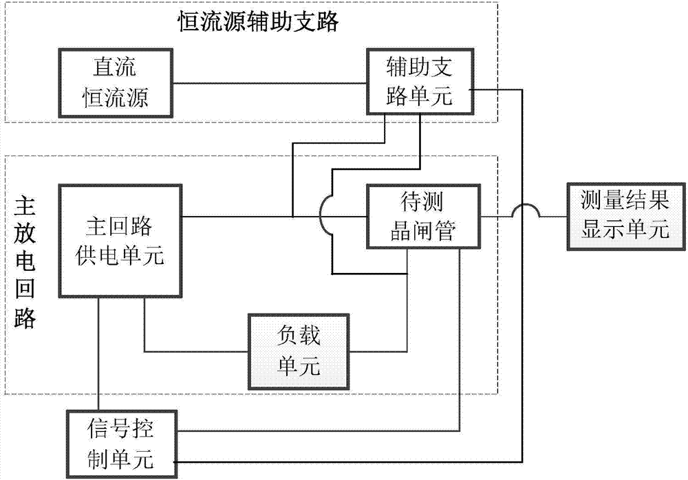
[0036]The system block diagram of the thyristor conducting voltage drop measurement system provided by the present invention is as follows figure 1 The shown includes: constant current source auxiliary branch, main discharge circuit, signal control unit and voltage measurement unit; the constant current source auxiliary branch is composed of DC constant current source and auxiliary branch unit; ...


PUM


Abstract

The invention discloses a thyristor breakover voltage drop measurement system and method. The thyristor breakover voltage drop measurement system comprises a constant current source auxiliary branch circuit, a main discharge circuit, a signal control unit and a measurement result displaying unit, wherein the constant current source auxiliary branch circuit is connected to the two ends of a thyristor to be measured in parallel, and the thyristor to be measured is both in a direct-current constant-current breakover state before or after pulse large current of the main discharge circuit flows across the thyristor to be measured. The measurement method is based on the measurement system, in order to solve the problem that the voltage of the thyristor can not be accurately measured when junction temperature is measured through a thermal sensitive parameter method, the direct-current constant current source auxiliary branch circuit is connected to the two ends of the thyristor to be measured in parallel, the thyristor to be measured is both in the direct-current constant-current breakover state before or after pulse large current of the main discharge circuit flows across the thyristor to be measured, the situation that breakover voltage drop of the thyristor to be measured is covered by blocking voltage of the two ends of the thyristor is avoided, and therefore accuracy of the breakover voltage drop measurement result of the thyristor is guaranteed.

Description

technical field [0001] The invention belongs to the technical field of voltage measurement, and more specifically relates to a thyristor conduction voltage drop measurement system and measurement method. Background technique [0002] The thermal parameter method is a junction temperature measurement method recommended by the International Electrotechnical Commission standard IEC60747, and the thyristor voltage is generally used as the thermal parameter. [0003] In the prior art, there is a problem of inaccurate measurement of the conduction voltage drop of the thyristor in the measurement of the junction temperature by the thermal parameter method. The current of the thyristor at the turn-on moment is close to zero, and the turn-on voltage drop is a small voltage value close to the threshold voltage; since the thyristor is in the blocking state before the current starts to rise, the blocking voltage is very high, and the blocking voltage drops There is a process, the decli...

Claims


Application Information

Patent Timeline
IPC IPC(8): G01R19/00
Inventor 戴玲张钦林福昌陈旭杨羊王勋郭啸龙
Owner HUAZHONG UNIV OF SCI & TECH
Why Eureka
Try Eureka