Air door temperature controller

A thermostat and damper technology, used in lighting and heating equipment, cooling fluid circulation devices, household appliances, etc., can solve the problems of noise caused by fans, small expansion and contraction of the temperature sensing tube, and insufficient opening of the damper to ensure stability. The effect of improving the gas storage capacity

Inactive Publication Date: 2015-06-17
CHANGZHOU THERMOSTER ELECTRICAL APPLIANCE
View PDF0 Cites 6 Cited by
  • Summary
  • Abstract
  • Description
  • Claims
  • Application Information

AI Technical Summary

Problems solved by technology

[0002] Traditional refrigerators are generally divided into two parts: the freezer and the refrigerator. The refrigerator and the freezer are connected by an air duct. The fan blows the cold air in the freezer to the refrigerator, and a temperature detection circuit controls the switch of the fan. This structure Not only does it require extra power to drive the fan to rotate, but it will also generate noise when the fan rotates, and the temperature in the refrigerator cannot be adjusted. Therefore, how to provide a temperature control device that saves energy, eliminates noise, and can adjust the temperature of the refrigerator has become an issue in front of people. The existing damper controller solves the above problems. The existing damper controller mainly controls the opening and closing of the damper through the thermal expansion and contraction of the temperature sensing cylinder. However, due to the limited storage space in the tail pipe, the stored The air volume is constant, and the expansion and contraction of the temperature sensing cylinder is small, which may cause the problem of insufficient opening of the damper

Method used


Image

  • Air door temperature controller

Examples


Embodiment Construction

[0011] The present invention will be further described below in conjunction with the accompanying drawings.

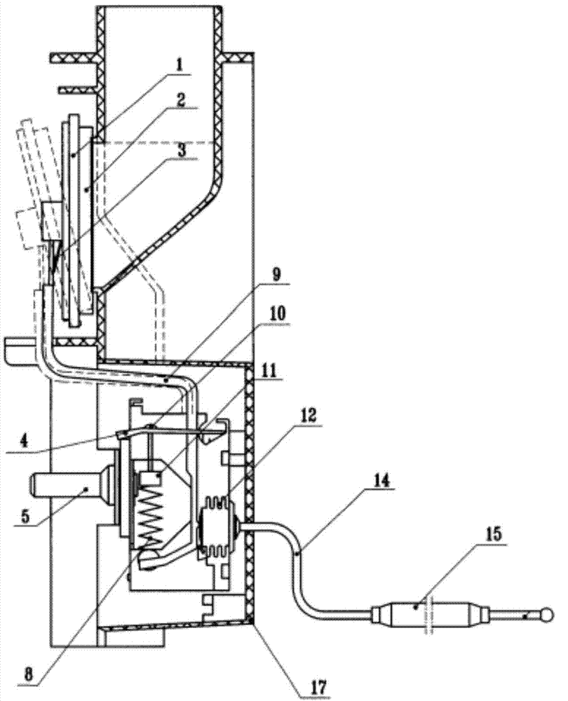
[0012] Such as figure 1 The damper thermostat shown includes a casing 17, an air inlet is arranged on the top of the casing 17, an air outlet is arranged on the left side, and a bellows 12 is arranged in the right side wall below the casing 17, and one end of the bellows 12 is connected with a temperature sensor through a capillary tube. The cylinder 15 and the tailpipe, the other end is provided with the active arm 9, the upper end of the active arm 9 is connected with the damper 1 corresponding to the air outlet of the shell, the sealing liner 2 is arranged between the damper 1 and the air outlet, and the damper 1 and the active arm 9 are provided with The reset piece 3, the adjusting cam 5 is fixed on the left side under the shell 17, the adjusting plate 4 is arranged above the adjusting cam 5, the adjusting screw 10 is arranged on the adjusting plate 4, the adjusti...


PUM


Abstract

The invention belongs to refrigerator accessories, and particularly relates to an air door temperature controller which comprises a shell. an air inlet is formed in the upper portion of the shell, an air outlet is formed in the left side of the shell, a corrugated pipe is arranged in the right side wall of the lower portion of the shell, one end of the corrugated pipe is connected with a temperature sensing cylinder and a tail pipe connected with a capillary, and a driving arm is arranged at the other end of the corrugated pipe. The upper end of the driving arm is connected with an air door corresponding to the air outlet of the shell. A sealing liner is arranged between the air door and the air outlet, a reset piece is arranged between the air door and the driving arm, an adjustment cam is fixed to the left side of the lower portion of the shell, an adjustment plate is arranged on the adjustment cam, an adjusting screw is arranged on the adjustment plate, an adjusting nut is screwed to the lower portion of the adjusting screw, a tension spring is connected to the bottom of the driving arm, and the upper end of the tension spring is fixedly connected to the adjusting nut. The air door temperature controller is characterized in that the temperature sensing cylinder is filled with activated carbon. A containing cavity increases the air storage quantity in the tail pipe, the expansion and retraction quantity of the temperature sensing cylinder is guaranteed, and the opening degree of the air door is guaranteed.

Description

technical field [0001] The invention belongs to refrigerator accessories, in particular to an air door temperature controller. Background technique [0002] Traditional refrigerators are generally divided into two parts, the freezer and the refrigerator. The refrigerator and the freezer are connected by an air duct. The fan blows the cold air in the freezer to the refrigerator, and a temperature detection circuit controls the switch of the fan. This structure Not only does it require extra power to drive the fan to rotate, but it will also generate noise when the fan rotates, and the temperature in the refrigerator cannot be adjusted. Therefore, how to provide a temperature control device that saves energy, eliminates noise, and can adjust the temperature of the refrigerator has become an issue in front of people. The existing damper controller solves the above problems. The existing damper controller mainly controls the opening and closing of the damper through the thermal ...

Claims


Application Information

Patent Timeline
Patent Type & Authority Applications(China)
IPC IPC(8): H01H37/38F25D29/00
CPCF25D17/045F25D29/005
Inventor 金彩凤
Owner CHANGZHOU THERMOSTER ELECTRICAL APPLIANCE
Why Eureka
Try Eureka