Eureka AIR delivers breakthrough ideas for toughest innovation challenges, trusted by R&D personnel around the world.

Valve stent safe to use and valve replacement device with same

一种瓣膜、安全的技术,应用在医疗器械领域,能够解决瓣膜无法正常释放、阻力大、安全隐患等问题,达到解决鞘管损坏问题、产品改性成本低、增加生产成本的效果

Active Publication Date: 2015-06-24
VENUS MEDTECH (HANGZHOU) INC
View PDF12 Cites 4 Cited by
  • Summary
  • Abstract
  • Description
  • Claims
  • Application Information

AI Technical Summary

Problems solved by technology

The valve sewing section in this patent document is composed of several diamond-shaped structural units. When the distal end of the valve sewing section is connected to the stop mechanism, there are several isolated diamond-shaped vertices left over. These isolated diamond-shaped vertices become security risks
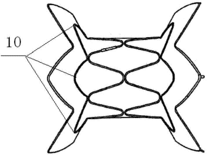
[0007] As another example, the Chinese patent document whose authorized announcement number is CN 101951858 B discloses a funnel-shaped throttling device, such as figure 1 As shown, the funnel-shaped throttling device includes a middle part with a rhombus grid structure, and flared end parts connected to both ends of the middle part. The rhombus grid structure in the middle part has a number of isolated rhombus vertices 10, which exist in isolation The rhombus vertex 10 will cause great inconvenience to the operation process
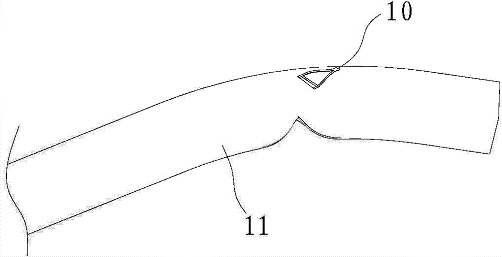
[0008] When the valve stent is compressed into the sheath, the isolated diamond-shaped vertices will be deformed into spikes, which will easily puncture the sheath when passing through the complex curved anatomical path of the human body, and will also cause resistance during the subsequent valve release process If it is too large, it will puncture the sheath, causing the valve to fail to release normally. In extreme cases, it will puncture or even pierce the blood vessel wall, causing great harm to the patient.

Method used


Image

  • Valve stent safe to use and valve replacement device with same
  • Valve stent safe to use and valve replacement device with same
  • Valve stent safe to use and valve replacement device with same

Examples


Embodiment 1

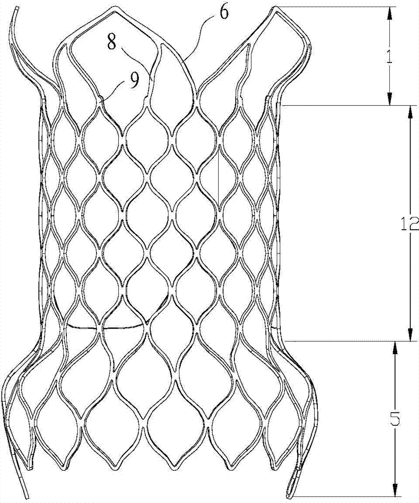
[0042] Such as image 3 As shown, a safe pulmonary artery stent is used, including a support grid 12 and an inflow section 5 and an outflow section 1 respectively connected to the two axial ends of the support grid 12 .

[0043] The radial expansion of the inflow section 5 and the outflow section 1 is flaring. When released in the human body, the outflow section 1 of the pulmonary artery stent is the first release end, and the outflow section 1 is connected to all end nodes 9 on the corresponding side of the supporting grid 12 . image 3 In , the posterior half of the valve stent is omitted, and only the anterior half of the valve stent is shown.

[0044] The outer edge of the outflow section 1 is surrounded by a number of curved support bars 6, and each adjacent four end nodes 9 are taken as a group, and in a group of end nodes 9, there is one support bar 6 and two connecting bars 8 , the two ends of the support bar 6 are respectively connected to the two end nodes 9 that ar...

Embodiment 2

[0047] Such as Figure 5 As shown, a safe pulmonary artery stent is used, including a support grid and an inflow section 5 and an outflow section 1 respectively connected to the axial ends of the support grid, and the middle part of the support grid is a transition section 3 .

[0048] Both ends of the transition section 3 are respectively connected to the inflow section 5 through the first mesh section 4 and connected to the outflow section 1 through the second mesh section 2 . The first grid segment 4 and the second grid segment 2 are respectively composed of continuous rhombuses. Compared with the transition segment 3, the first grid segment 4 expands outward in the radial direction to form a flaring. The sides of the rhombus are not strictly straight lines, but slightly Bending outwards, the number of rhombuses in the first mesh segment 4 and the second mesh segment 2 is the same.

[0049] The transition section 3 is composed of several straight rods 7 extending axially a...


PUM


Abstract

The invention discloses a valve stent safe to use and a valve replacement device with the same. The valve stent comprises a tubular supporting net rack and a flaring section connected to the end of the supporting net rack. The flaring section is connected with all end nodes of the corresponding side of the supporting net rack. The flaring section is located at the initial releasing end of the valve stent. The outer edge of the flaring section is formed by a plurality of bent supporting strips. The end nodes, corresponding to the supporting strips in position, of the supporting net rack are connected with the supporting strips. The structure of an existing memory alloy self-expanding valve stent is improved, isolated rhombus peaks existing at the non-end portion of the valve stent are eliminated, the phenomenon that spines appear after the valve stent is compressed is avoided while the original structural mechanical property is kept, and the problem that a sheathing canal is damaged by spines is fundamentally solved.

Description

technical field [0001] The invention relates to the field of medical devices, in particular to a safe valve support and a valve replacement device with the valve support. Background technique [0002] In the prior art, an interventional heart valve usually includes a compressible valve stent and valve leaflets, wherein the valve stent has good biocompatibility and can be safely, stably and reliably placed on a corresponding heart valve position. [0003] The main part of the valve stent is mostly a diamond-shaped unit structure to meet the compressibility requirements. However, the diamond-shaped unit structure will have independent diamond-shaped vertices. These isolated rhombus-shaped vertices are usually relatively sharp. During the use of the valve stent, These isolated diamond-shaped vertices pose a risk of puncturing the sheath. [0004] If these isolated diamond-shaped vertices are concentrated at the end of the valve stent, the piercing effect will be small. However...

Claims


Application Information

Patent Timeline
Patent Type & Authority Applications(China)
IPC IPC(8): A61F2/24
CPCA61F2/2412A61F2/2418A61F2/2436A61F2230/001A61F2230/005A61F2250/0039A61F2220/0025A61F2210/0014A61F2230/0078A61F2250/0026
Inventor 曾敏罗拉里齐均
Owner VENUS MEDTECH (HANGZHOU) INC
Why Eureka
Eureka Blog
Learn More