
Hydraulic locking device of pressure machine

A locking device and press technology, applied in the field of press locking, can solve the problems of affecting precision, low precision of stamping workpiece quality, reducing screw 2' and press die service life, etc., to improve precision and eliminate thread clearance , The effect of high precision of screw movement

Inactive Publication Date: 2015-06-24
浙江嚞锻机床有限公司
View PDF6 Cites 4 Cited by
  • Summary
  • Abstract
  • Description
  • Claims
  • Application Information

AI Technical Summary

Problems solved by technology

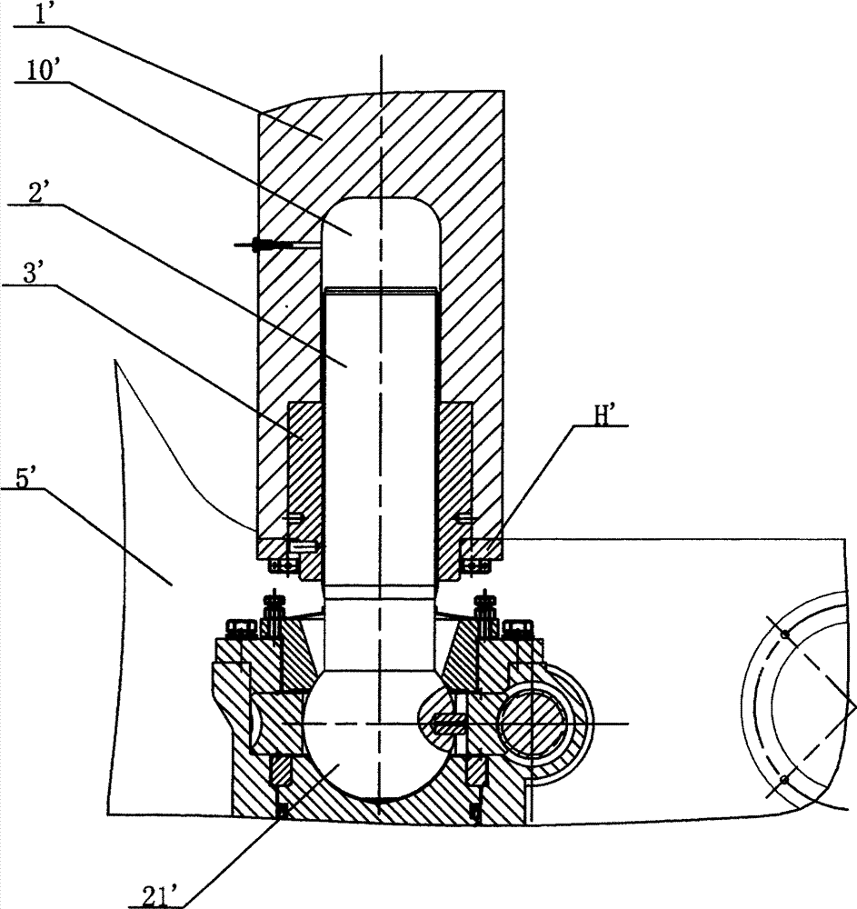
[0004] When the press is working, the movement of the known crankshaft and connecting rod mechanism makes the connecting rod 1' drive the screw ball head 21' to move, so that the movement is transformed into the slider 5' moving up and down at the upper dead center position and the lower dead center working position, There is an objective thread gap between the screw 2' and the screw sleeve 3', which affects the accuracy of the slider 5' reaching the bottom dead point, resulting in low quality and accuracy of the stamping workpiece, and also reduces the service life of the screw 2' and the press die

Method used


Image

  • Hydraulic locking device of pressure machine
  • Hydraulic locking device of pressure machine

Examples


Embodiment Construction

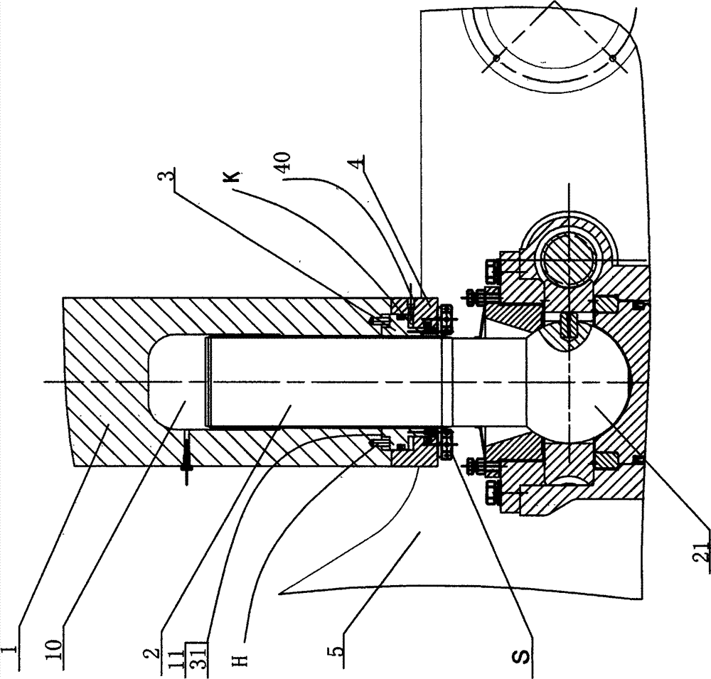
[0014] Please refer to figure 2 As shown, a hydraulic locking device for a press includes a connecting rod 1 with a stepped hole 10 and a screw 2 located in the stepped hole 10, the length of the screw 2 is such that it can extend outside the stepped hole 10, and the screw 2. The end protruding from the step hole 10 forms a screw ball head 21, which is connected to the slider 5. The improvement is that it also includes a lock nut 3 installed on the step hole 10. The lock nut 3 is installed so that Its top plane 31 has a certain axial clearance relative to the step 11. When the screw rod 2 and the lock nut 3 are screwed together, there is a certain thread clearance. The axial clearance is greater than this thread clearance. A sealing end cover 4 with a radial through hole 40 is fixedly installed on the bottom end surface, an axial separation cavity K is formed between the sealing end cover 4 and the lock nut 3, and the axial separation cavity K communicates with the radial thr...


PUM


Abstract

The invention discloses a hydraulic locking device of a pressure machine. The hydraulic locking device of the pressure machine comprises a connecting rod with a stepped hole, a locknut installed on the stepped hole, and a screw located in the stepped hole, the screw can stretch out of the stepped hole in the length direction, a screw ball head is formed at the stretching end of the screw and connected with a sliding block, the top plane of the locknut has a certain axial clearance relative to a step, the screw and the locknut have a certain thread clearance when screwed together, and the axial clearance is larger than the thread clearance. A seal end cover with a radial through hole is installed on the bottom end face of the connecting rod, an axial separation cavity is formed between the seal end cover and the locknut and communicated with the radial through hole, and when hydraulic oil is injected into the radial through hole and the axial separation cavity is filled with the hydraulic oil, the screwed section of the locknut and the screw rod has elastic deformation. By the adoption of the technical scheme, the thread clearance can be eliminated, the screw is high in movement precision and long in service life, the precision of the sliding block moving to a bottom dead centre working position is improved, and therefore a stamped workpiece has high quality and precision.

Description

【Technical field】 [0001] The invention relates to a hydraulic locking device of a press, belonging to the technical field of press locking. 【Background technique】 [0002] Such as figure 1 Shown, the locking device of existing press comprises connecting rod 1 ', screw rod 2 ' and screw sleeve 3 ', and screw rod 2 ' and screw sleeve 3 ' are all located in the stepped hole 10 ' of connecting rod 1 '. Among them, the screw sleeve 3' is fixed in the stepped hole 10' through the pressure plate H', the screw sleeve 3' and the screw rod 2' are screwed together through internal and external threads, and the end of the screw rod 2' protruding from the stepped hole 10' forms a A screw ball head 21', the screw ball head 21' is connected to the slider 5'. [0003] Slider 5' up and down reciprocating process is as follows: [0004] When the press is working, the movement of the known crankshaft and connecting rod mechanism makes the connecting rod 1' drive the screw ball head 21' to m...

Claims


Application Information

Patent Timeline
IPC IPC(8): B30B15/00
Inventor 黄平钗王晓燕周旗英王枫华黄龙洁
Owner 浙江嚞锻机床有限公司
Learn More