
Evaporating device

A technology of evaporation and evaporation source, which is applied in the direction of vacuum evaporation coating, sputtering coating, ion implantation coating, etc., can solve the problems of long transmission and vacuuming time, complicated equipment, etc., and save vacuuming time, save The effect of teleportation time

Active Publication Date: 2015-06-24
BOE TECH GRP CO LTD +1
View PDF5 Cites 15 Cited by
  • Summary
  • Abstract
  • Description
  • Claims
  • Application Information

AI Technical Summary

Problems solved by technology

The above-mentioned evaporation device needs to set up a transfer chamber separately, and every evaporation needs to re-evacuate each evaporation chamber, the equipment is complex, and the transfer and vacuuming time is long

Method used


Image

  • Evaporating device
  • Evaporating device
  • Evaporating device

Examples


Embodiment 1

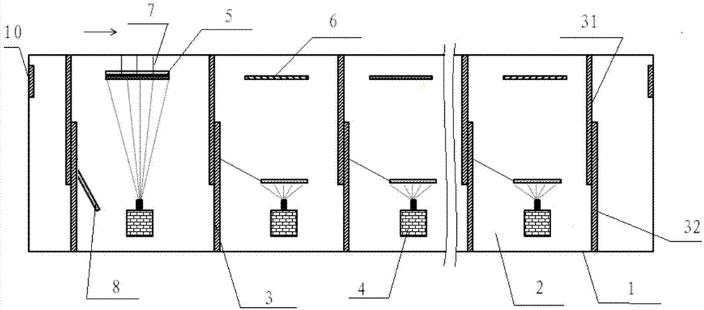
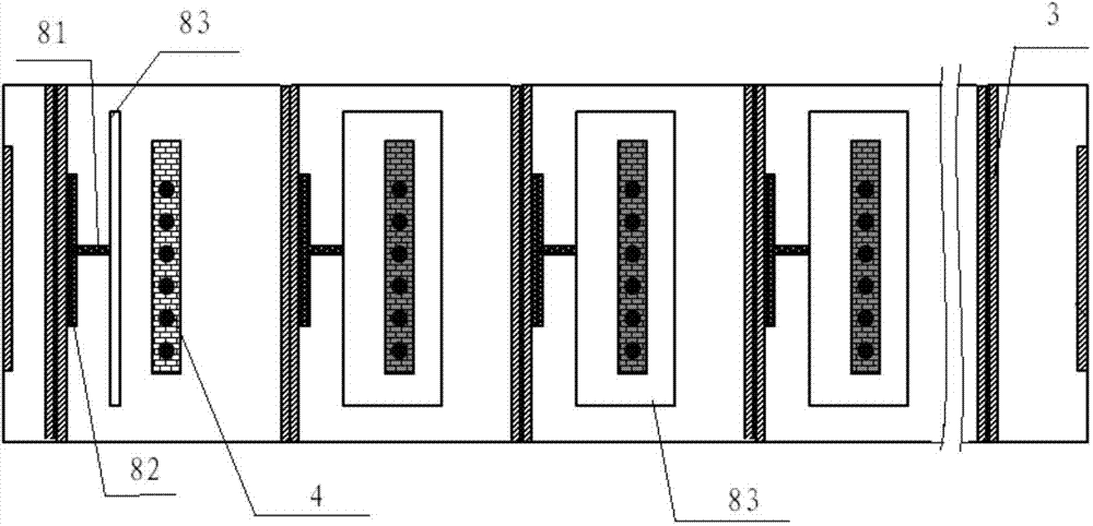
[0031] Such as Figure 1-8 As shown, this embodiment provides an evaporation device, including an evaporation chamber 1 for evaporating a substrate 11 to be evaporated, and the evaporation chamber 1 includes: a plurality of evaporation sub-chambers 2, and An isolation unit 3 located between adjacent evaporation sub-chambers 2 that can isolate adjacent evaporation sub-chambers 2, each of the evaporation sub-chambers 2 includes Evaporation source 4 at one end;

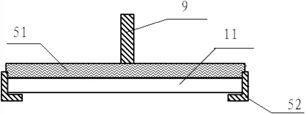
[0032] And a transfer unit 5 which is arranged opposite to the evaporation source 4 and carries the substrate to be evaporated 11 to move between the evaporation sub-chambers 2 .

[0033] The evaporation device of this embodiment includes a plurality of evaporation sub-chambers, the substrate to be evaporated is moved in the plurality of evaporation sub-chambers to complete the evaporation of each layer, saving the transfer time of the substrate to be evaporated, and the evaporation chamber The chamber is maintained in...


PUM


Abstract

The invention provides an evaporating device and aims to solve the problems that an evaporating device in the prior art needs to be provided with an independent conveying chamber, evaporating chambers need to be vacuumed again for evaporation every time, the evaporating device is complex in equipment and long in conveying and vacuuming time and the like. The provided evaporating device comprises a plurality of evaporating sub-chambers. The evaporating device has the advantages that evaporation in layers is completed by moving a to-be-evaporated base plate among the evaporating sub-chambers, so that conveying time of the to-be-evaporated base plate is saved; by maintaining the evaporating sub-chambers in a same vacuum environment, the evaporating sub-chambers need not to be vacuumed again, so that vacuuming time is saved.

Description

technical field [0001] The present invention relates to the technical field of manufacturing electronic components, in particular to an evaporation device. Background technique [0002] Evaporation devices for evaporating organic materials are generally designed to include multiple independent evaporation chambers. Each evaporation chamber needs to independently control the vacuum degree. Each evaporation chamber evaporates a material. When it needs to be deposited on the substrate to be evaporated When evaporating multiple substances, it is necessary to set up a separate transfer chamber to transfer the substrate to be evaporated between each independent evaporation chamber; when the substrate to be evaporated enters each evaporation chamber, it is necessary to re-evacuate each evaporation chamber . The above-mentioned evaporation device requires a separate transfer chamber, and each evaporation chamber needs to be evacuated again for each evaporation, the equipment is com...

Claims


Application Information

Patent Timeline
Patent Type & Authority Applications(China)
IPC IPC(8): C23C14/24
CPCC23C14/568C23C14/24C23C14/042
Inventor 裴凤巍赵子仪崔富毅张金中
Owner BOE TECH GRP CO LTD
Learn More