substrate fixing device

A technology for fixing devices and substrates, applied in ion implantation plating, metal material coating process, coating, etc., can solve problems such as abnormal discharge and affecting coating effect, and achieve the effect of saving operating costs and improving coating effect

Active Publication Date: 2017-06-16
BOE TECH GRP CO LTD +1
View PDF9 Cites 1 Cited by
  • Summary
  • Abstract
  • Description
  • Claims
  • Application Information

AI Technical Summary

Problems solved by technology

[0003] However, in actual production, the inventors of the present application have found that the material of the ITO film plated in the sputter coating process is easy to fall into the gap between the substrate and the metal frame carrying the substrate, and the ITO film falling into the gap The material is easy to directly conduct the ITO film and the metal frame during the sputtering coating process, resulting in abnormal discharge phenomenon, which affects the coating effect

Method used


Image

  • substrate fixing device

Examples


Embodiment Construction

[0016] The following will clearly and completely describe the technical solutions in the embodiments of the present invention with reference to the accompanying drawings in the embodiments of the present invention. Obviously, the described embodiments are only some, not all, embodiments of the present invention. Based on the embodiments of the present invention, all other embodiments obtained by persons of ordinary skill in the art without making creative efforts belong to the protection scope of the present invention.

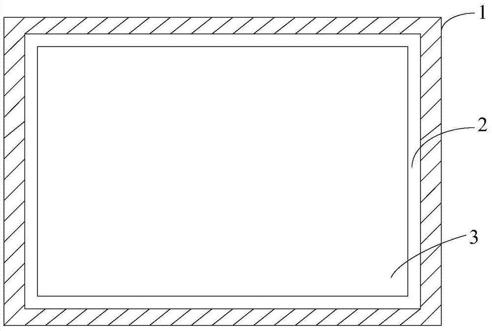
[0017] figure 1 It is a schematic cross-sectional structure diagram of the substrate fixing device provided by the embodiment of the present invention. like figure 1 As shown, a substrate fixing device includes a metal frame main body 1, the central part of the metal frame main body 1 is provided with a through hole 3 consistent with the area to be coated on the substrate, and the metal frame main body 1 is provided with a In the groove 2 of the carrier subs...


PUM

PropertyMeasurementUnit
thermal resistanceaaaaaaaaaa

Abstract

A substrate fixing apparatus includes a metal frame body. A central portion of the metal frame body is provided with a through hole; a recess configured for bearing a substrate is formed on the metal frame body along an edge of the through hole; the recess is recessed towards an inside of the metal frame body along a thickness direction of the metal frame body; and a first insulating pad is disposed at the bottom of the recess.

Description

technical field [0001] The invention relates to the field of display technology, in particular to a display substrate fixing device. Background technique [0002] At present, in the production process of display substrates such as color filter substrates, when the ITO film is coated on the display substrate, due to the needs of sputter coating equipment, the display substrate needs to be hung vertically on the metal frame and sent to the sputter coating equipment. In this way, the coating can be completed. [0003] However, in actual production, the inventors of the present application have found that the material of the ITO film plated in the sputter coating process is easy to fall into the gap between the substrate and the metal frame carrying the substrate, and the ITO film falling into the gap The material is easy to directly conduct the ITO film and the metal frame during the sputtering coating process, resulting in abnormal discharge phenomenon, which in turn affects ...

Claims


Application Information

Patent Timeline
Patent Type & Authority Patents(China)
IPC IPC(8): C23C14/50C23C14/35
CPCC23C14/50
Inventor 王华龙
Owner BOE TECH GRP CO LTD
Why Eureka
Try Eureka