A rotating platform mechanism for detecting cables

A technology for rotating platforms and cables, used in measuring devices, bridge parts, erecting/assembling bridges, etc., can solve the problems of backward inspection and maintenance methods of oblique cables, cumbersomeness, and high energy consumption, so as to improve detection accuracy and range of motion. Large, cost-saving effect

Active Publication Date: 2016-08-31
武汉恒兴通检测有限公司 +1
View PDF7 Cites 0 Cited by
  • Summary
  • Abstract
  • Description
  • Claims
  • Application Information

AI Technical Summary

Problems solved by technology

So far, the inspection and maintenance methods for inclined cables are still relatively backward. In the early days, the hoist was used to move the equipment along the cable, and the test data was recorded or stored for analysis; The friction wheel is pressed to make the robot climb continuously or the air-driven cylinder is clamped to creep and climb. Using the accompanying spraying, magnetic detection and other devices, the coating and internal inspection of the in-service cables are realized. Disadvantages: such as relatively bulky, large energy consumption and other shortcomings

Method used


Image

  • A rotating platform mechanism for detecting cables
  • A rotating platform mechanism for detecting cables
  • A rotating platform mechanism for detecting cables

Examples


Embodiment 1

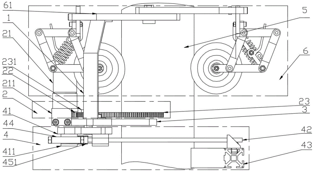
[0037] like Figure 1 to Figure 5 As shown, a rotating platform mechanism for detecting cables includes a connecting rib 1 , a positioning member fixedly connected to the connecting rib 1 , and a driving device 2 and a measuring device 4 connected to the positioning member. The positioning member is a guide rail 3 , the driving device 2 is located above the guide rail 3 , and the measuring device 4 is located below the guide rail 3 .

[0038] Drive device 2 comprises motor support base 211, reduction motor 21, first gear 22 and second gear 23; Motor support base 211 is fixedly connected with guide rail 3, and reduction motor 21 is fixedly connected on the motor support base 211, and first gear 22 passes through The bearing is fixedly connected on the motor support base 211, the first gear 22 cooperates with the output shaft of the reduction motor 21, and the first gear 22 meshes with the second gear 23; the second gear 23 is arc-shaped.

[0039] The measurement device 4 inclu...

Embodiment 2

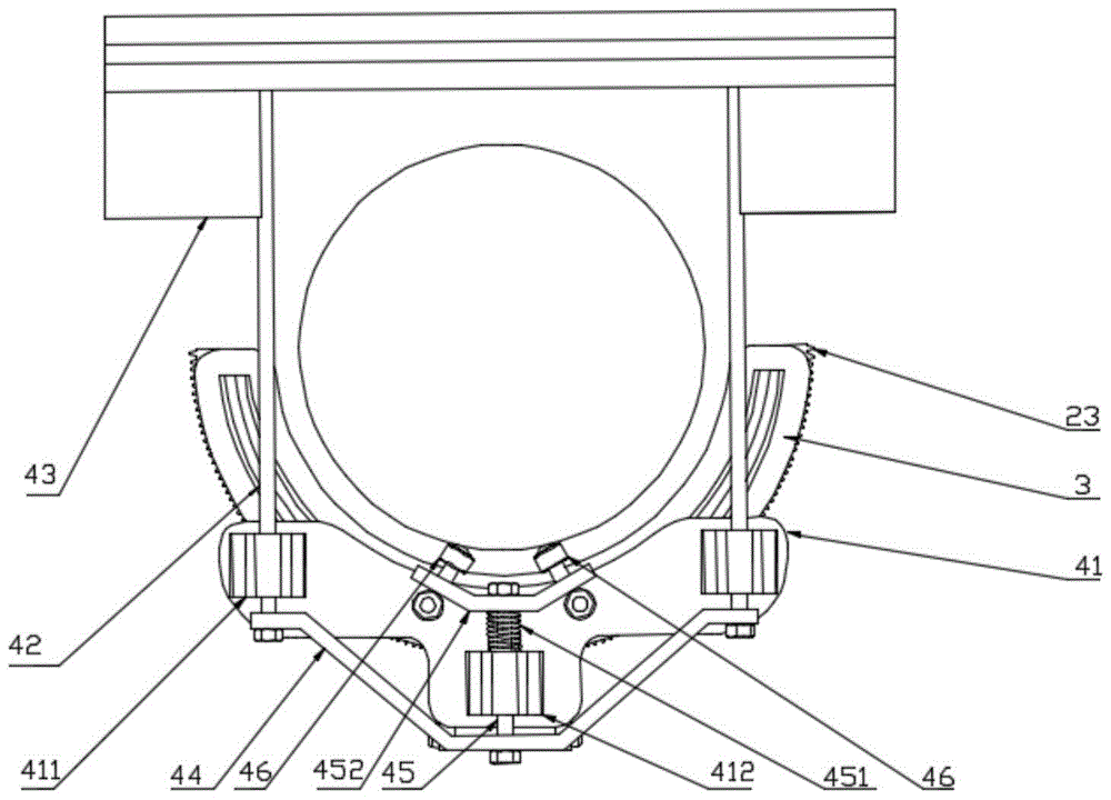
[0045] like Image 6 and Figure 7 As shown, a cable-based rotary platform mechanism includes a connecting rib 1 , a positioning member fixedly connected to the connecting rib 1 , and a driving device 2 and a measuring device 4 connected to the positioning member. The positioning member is a guide rail 3 , the driving device 2 is located above the guide rail 3 , and the measuring device 4 is located below the guide rail 3 .

[0046] The driving device 2 includes a geared motor 21, a first connecting rod 24, a second connecting rod 25 and a slide block 26; the geared motor 21 is fixedly connected to the guide rail 3, and one end of the first connecting rod 24 is fixedly connected to the output shaft of the geared motor 21 Above, the other end of the first connecting rod 24 is connected to one end of the second connecting rod 25 by a sliding bolt, and the other end of the second connecting rod 25 is connected to the slider 26 by a second sliding bolt 261, and the slider 26 is a...

Embodiment 3

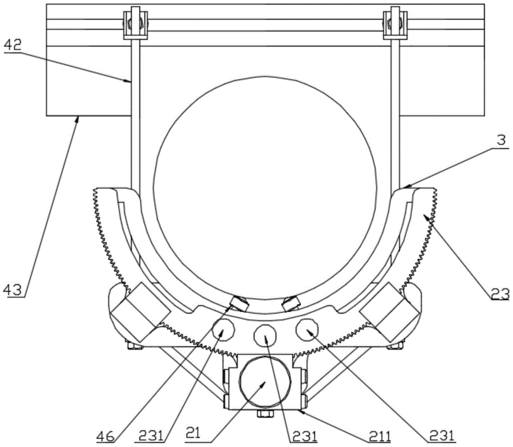
[0052] like Figure 8 and Figure 9 As shown, a cable-based rotary platform mechanism includes a connecting rib 1 , a positioning member fixedly connected to the connecting rib 1 , and a driving device 2 and a measuring device 4 connected to the positioning member. The positioning member includes an adjustable connecting member 31 , a first connecting plate 481 and a second connecting plate 482 . The first connecting plate 481 and the second connecting plate 482 are fixedly connected to two ends of the adjustable connecting member 31 .

[0053] The structure of the adjustable connecting piece 31 can be various. by Figure 9 For example, there are two adjustable connecting pieces 31 . Each adjustable connecting piece 31 is provided with a row of parallel slotted holes, and the slotted holes of the two adjustable connecting pieces 31 are aligned and fixedly connected with positioning bolts. The adjustment of the cable radius by the rotating platform can be realized through ...


PUM


Abstract

The invention discloses a rotating platform mechanism used for detecting a cable. The rotating platform mechanism comprises a connecting rib plate, a positioning part, a driving device and a measuring device, wherein the positioning part is fixedly connected with the connecting rib plate, the driving device and the measuring device are connected with the positioning part, the driving device is used for rotating the measuring device, and the measuring device is used for measuring the size of the cable. The rotating platform mechanism can rotate around the cable, so that the sizes of different positions of the cable are measured accurately, and the damage situations of protrusions or grooves of the surface of the cable are detected.

Description

technical field [0001] The invention belongs to the technical field of robot application, and in particular relates to a rotating platform mechanism for detecting cables. Background technique [0002] With the rapid development of economy and transportation, the development of long-span bridges is getting faster and faster. As a new type of modern bridge, cable-stayed bridges have been widely used in the world. After the completion of cable-stayed bridges and suspension bridges, the cables, one of the main stress-bearing components, will be exposed to the air for a long time, and the polyethylene (PE) protective layer on the surface of the cables will show different degrees of hardening and aging. Corroded by moisture and other acidic substances in the air, and even broken wires in severe cases, endangering the safety of the bridge. Up to now, there have been several unfortunate engineering examples in which all cables of cable-stayed bridges have been replaced due to serio...

Claims


Application Information

Patent Timeline
Patent Type & Authority Patents(China)
IPC IPC(8): E01D22/00
CPCE01D19/106G01B21/00
Inventor 王兴松戴苏亚刘世亮王蔚
Owner 武汉恒兴通检测有限公司
Why Eureka
Try Eureka