Self-gasification combustor

A burner and combustion chamber technology, applied in the directions of burners, burners, liquid fuel burners, etc., can solve the problems of high cost, unfavorable installation, inconvenient maintenance, etc., and achieve the effect of increasing the scope of use and convenient transportation

Active Publication Date: 2015-06-24
HEFEI EQUIP IND EQUIP
View PDF5 Cites 2 Cited by
  • Summary
  • Abstract
  • Description
  • Claims
  • Application Information

AI Technical Summary

Problems solved by technology

From an economic point of view, the cost of such a large pipe diameter is very expensive, because the large diameter of the pipe is not c

Method used


Image

  • Self-gasification combustor
  • Self-gasification combustor
  • Self-gasification combustor

Examples


Embodiment

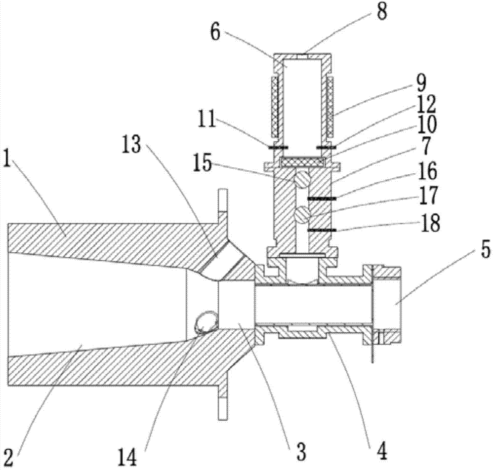
[0021] Embodiment: In conjunction with the accompanying drawings, the self-gasification burner of this embodiment includes:

[0022] The inner cavity of the burner body 1 is the combustion chamber 2, and the end of the burner body at the entrance of the combustion chamber 2 is set as the mixing chamber 3; the burner body between the combustion chamber 2 and the mixing chamber 3 is provided with an ignition port 13 And the fire port 14.

[0023] A gas and air passage 4 is provided, the inlet end of the gas and air passage is the combustion air inlet 5 , and the outlet end communicates with the mixing chamber 3 .

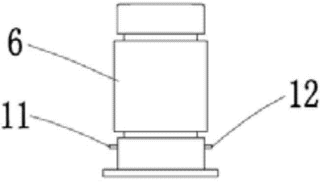
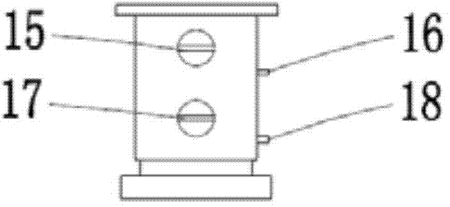
[0024] A gasification chamber 6 and a pressure regulator 7 connected to the outlet end of the gasification chamber are provided, wherein the inlet end of the gasification chamber 6 is a liquid combustible gas inlet 8, and the outlet end of the pressure regulator communicates with the gas and air channels 4. The outside of the gasification chamber 6 is surrounded by a...


PUM


Abstract

The invention discloses a self-gasification combustor. An inner cavity of a combustor body is a combustion chamber. A mixing chamber is arranged at the end, at the inlet of the combustion chamber, of a combustor body. A gas and air channel is arranged. The inlet end of the channel is provided with a combustion air inlet, and the outlet end of the channel is communicated with the mixing chamber. A gasification chamber and a pressure adjuster connected to the outlet end of the gasification chamber are arranged. The inlet end of the gasification chamber is provided with a liquid state combustible gas inlet. The outlet end of the pressure adjuster is communicated with the gas and air channel. An electric heating device is arranged outside the gasification chamber in a surrounding mode. The outlet end of the gasification chamber is provided with an electric heating net. The upper portion of the electric heating net is provided with a temperature sensor and a pressure sensor. A first-stage pressure adjusting rod, a first-stage pressure sensor, a second-stage pressure adjusting rod and a second-stage pressure sensor are arranged in the pressure adjuster in sequence from top to bottom. The self-gasification combustor is a mechanical and electrical integrated device which has the maneuverability and can achieve self-gasification, and can directly use liquid state combustible gas by means of the structural features of itself.

Description

Technical field: [0001] The invention relates to a burner, which is mainly used in industrial combustion equipment, and is a burner capable of vaporizing liquid combustible gas within the range of the burner itself. Background technique: [0002] The combustible gas burner inlets used in the current industrial combustion system are all gaseous, so for some burners with relatively large combustion power, the delivery pipes and corresponding combustion equipment are very large, which is very inconvenient for maintenance and repair. Sometimes it is not easy to detect gas leaks, and it also limits the matching of other equipment. [0003] Taking a 2MW internal mixing burner as an example, the gas inlet size is DN80. If the combustible gas is transported according to this size, the gas pipeline will be relatively thick. From an economic point of view, the cost of such a large pipe diameter is very expensive. Because the pipe diameter is very large, it is not conducive to install...

Claims


Application Information

Patent Timeline
IPC IPC(8): F23D11/44F23D11/46
CPCF23D11/00F23D11/448F23D11/46F23D2202/00F23D2208/10
Inventor 陆守祥
Owner HEFEI EQUIP IND EQUIP
Why Eureka
Try Eureka