
DC bus capacitor voltage equalizing device

A technology of DC bus capacitor and voltage equalizing device, which is applied in the direction of output power conversion device, DC power input conversion to DC power output, electrical components, etc., which can solve the problem of rising ambient temperature, completely consistent capacitance parameters, and lack of versatility and other issues to achieve the effect of low energy loss

Inactive Publication Date: 2015-06-24
BEIJING JIAOTONG UNIV
View PDF5 Cites 4 Cited by
  • Summary
  • Abstract
  • Description
  • Claims
  • Application Information

AI Technical Summary

Problems solved by technology

[0003] However, because it is difficult to ensure that the parameters of the capacitor are completely consistent during the manufacturing and use process, a small difference in capacitance or leakage current will cause the voltage across the capacitor to be inconsistent.
If the voltage difference on each capacitor is very large, it will not only shorten the service life of the capacitor, but also cause damage to the capacitor in severe cases, affecting other circuits connected in parallel with the capacitor. Therefore, in actual use, some voltage equalization methods are generally used to ensure that each The voltage across the capacitor is equal
[0004] For example, it is possible to equalize the voltage by connecting resistors in parallel to each series capacitor, but this method will reduce the efficiency of the converter and generate heat significantly, which will increase the ambient temperature and is not conducive to the operation of the converter
In addition, a clamping circuit can be added to ensure that the voltage on the capacitor does not exceed its rated voltage, but this method cannot achieve voltage equalization of the capacitor
In addition, some converters achieve voltage equalization by adding some control strategies, but these methods usually need to collect the deviation voltage of the capacitor and the control method is complicated and not universal

Method used


Image

  • DC bus capacitor voltage equalizing device
  • DC bus capacitor voltage equalizing device
  • DC bus capacitor voltage equalizing device

Examples


Embodiment Construction

[0028] Embodiments of the present invention are described in detail below, examples of which are shown in the drawings, wherein the same or similar reference numerals designate the same or similar elements or elements having the same or similar functions throughout. The embodiments described below by referring to the figures are exemplary only for explaining the present invention and should not be construed as limiting the present invention.

[0029] The following disclosure provides many different embodiments or examples for implementing different structures of the present invention. To simplify the disclosure of the present invention, components and arrangements of specific examples are described below. Of course, they are only examples and are not intended to limit the invention. Furthermore, the present invention may repeat reference numerals and / or letters in different instances. This repetition is for the purpose of simplicity and clarity and does not in itself indicat...


PUM


Abstract

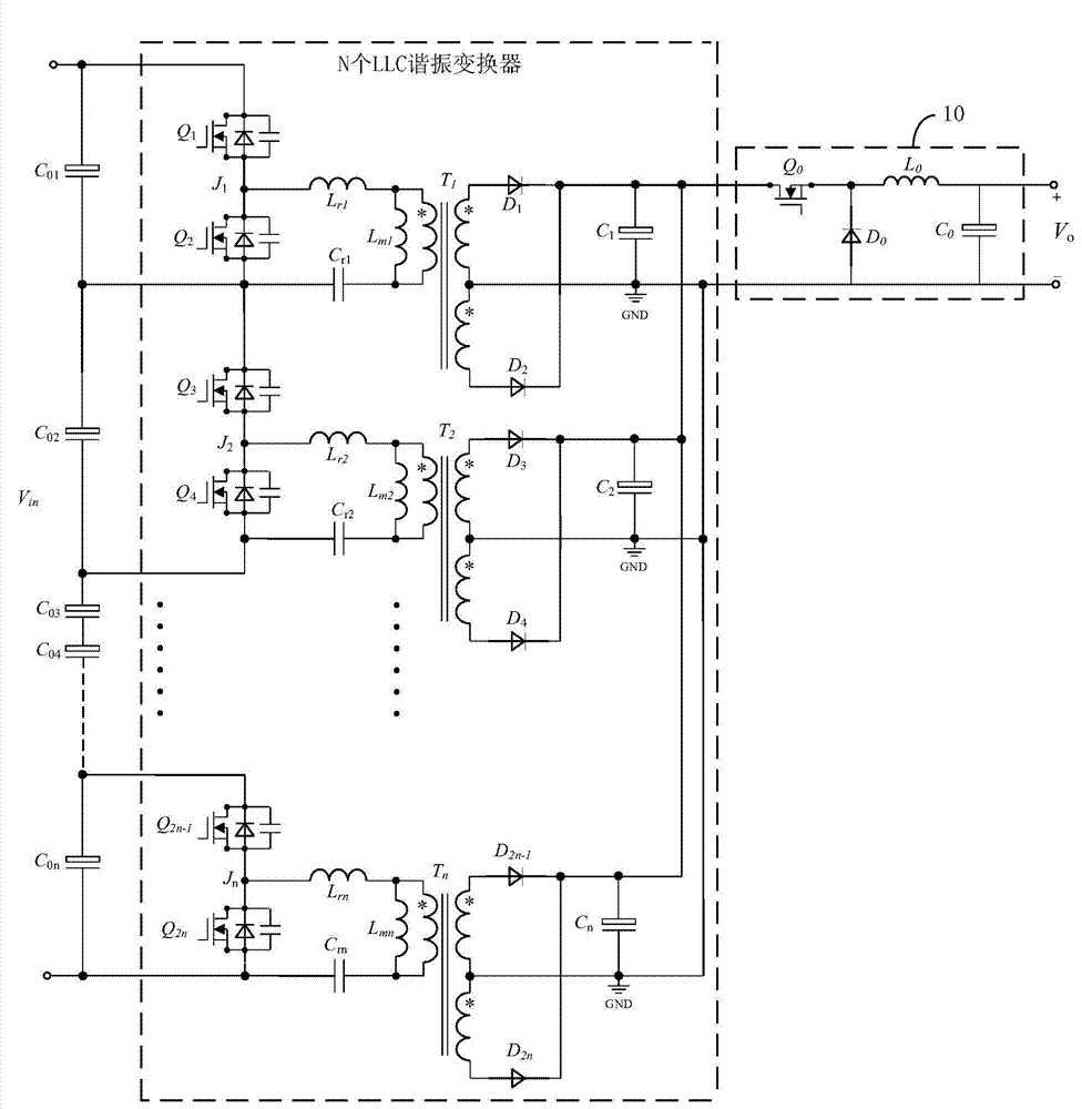
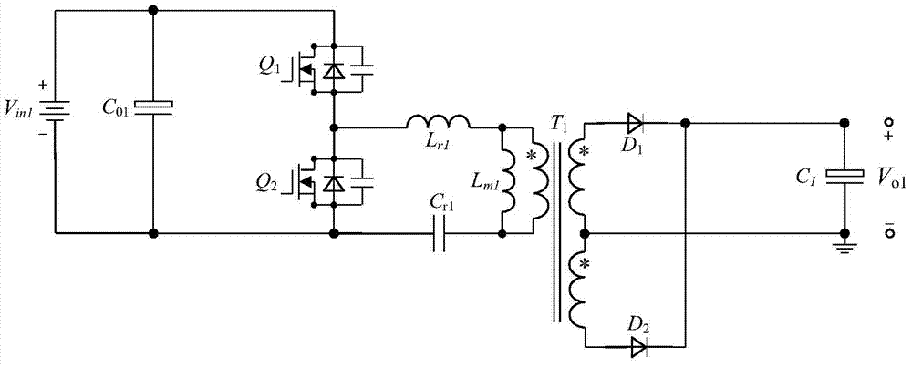
The invention discloses a DC bus capacitor voltage equalizing device. A DC bus capacitor comprises N capacitor bodies which are connected in series, wherein N is an integer larger than 1. The voltage equalizing device comprises N LLC resonant converters and a Buck circuit, wherein the N capacitor bodies which are connected in series are correspondingly connected with the N LLC resonant converters in a one-to-one mode, the output ends of the N LLC resonant converters are connected in parallel, and the N LLC resonant converters work at respective series resonance points; the Buck circuit is connected with the output ends of the N LLC resonant converters, and the Buck circuit is used for conducting closed-loop regulation on the N LLC resonant converters to output stable DC voltage. The voltage equalizing device can equalize voltage of the DC bus capacitor and is low in energy loss.

Description

technical field [0001] The invention relates to the technical field of voltage equalization of capacitors, in particular to a voltage equalization device for DC bus capacitors. Background technique [0002] The development trend of modern power electronic devices is high voltage, large capacity and high frequency. In more and more cases, the capacitor on the input side needs to use a capacitor with a larger capacitance and a higher withstand voltage value. Aluminum electrolytic capacitors are widely used due to their large capacitance and low price. However, because their maximum withstand voltage is 450V, two or more aluminum electrolytic capacitors are generally used in series when the voltage on the input side is high. [0003] However, because it is difficult to ensure that the parameters of the capacitor are completely consistent during the manufacturing and use process, a small difference in capacitance or leakage current will cause the voltage across the capacitor to...

Claims


Application Information

Patent Timeline
Patent Type & Authority Applications(China)
IPC IPC(8): H02M1/34H02M3/335
CPCH02M3/33507H02M1/0048H02M1/007H02M1/0083Y02B70/10
Inventor 郝瑞祥贺涛游小杰李艳郑琼林刘建强杨中平林飞郭希铮李虹黄先进
Owner BEIJING JIAOTONG UNIV
Learn More