Wave beam recognition method, related device and system for MIMO beam forming communication system

A communication system and beamforming technology, which is applied in the field of beam identification in the MIMO beamforming communication system, can solve the problems that the base station cannot use the beam to cover the terminal, the terminal cannot reach the coverage area of ​​the base station, and the base station cannot know the terminal, etc.

Active Publication Date: 2015-06-24
ZTE CORP
View PDF6 Cites 83 Cited by
  • Summary
  • Abstract
  • Description
  • Claims
  • Application Information

AI Technical Summary

Problems solved by technology

However, in this case, when a high carrier frequency is used for communication, the base station cannot use the optimal beam to cover the terminal before obtaining the beamforming weight, so the terminal cannot use the reference signal sent by the base station for measurement; Or even if the base station covers the terminal, the terminal cannot achieve the same coverage as the base station, so the base station cannot know the content fed back by the terminal. In this way, the base station cannot perform beamforming weight selection and normal communication

Method used


Image

  • Wave beam recognition method, related device and system for MIMO beam forming communication system
  • Wave beam recognition method, related device and system for MIMO beam forming communication system
  • Wave beam recognition method, related device and system for MIMO beam forming communication system

Examples


Embodiment 1

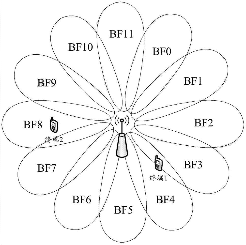
[0134] In this embodiment, it is assumed that the maximum number of beams supported by the base station is N, each beam is sent periodically, and the sending periods of the N beams are the same, and N training time-domain units are divided into each sending period, and N The training time-domain units form a training cycle, each training time-domain unit corresponds to a beam, and each training time-domain unit corresponds to an index number. Here, N=12 is taken as an example, as shown in Figure 5(a) and Figure 5(b) shown. Adjacent training time-domain units can be continuous in time, as shown in Figure 5(a); adjacent training time-domain units can also have a certain interval in time, as shown in Figure 5(b).

[0135] Assuming that the transmission cycle of the beam is T, there should be T≥N*t to ensure that there is enough time in each transmission cycle to send the beam training signal in each direction supported by the base station once; where t represents the training tim...

Embodiment 2

[0143] In this embodiment, it is assumed that the maximum number of beams supported by the base station is N, and each beam is transmitted periodically, but the transmission period corresponding to each beam is different, that is, there are N different transmission periods, corresponding to N beams respectively, N The sending cycles are denoted as t 0 ~t N-1 . A training time-domain unit is respectively divided in N different sending periods, and each training unit corresponds to an index number. The sending period of each beam may also be referred to as a time interval for sending the beam, and there are N different time intervals in total. In order to avoid false detection between beams, it is necessary to ensure that the time interval between different beams is not equal to the sending period of any beam; for example, assuming that there are two beams, the first beam and the second beam, the sending period of the first beam The transmission period of the second beam is 5...

Embodiment 3

[0152] In this embodiment, it is assumed that the maximum number of beams supported by the base station is N, and beam training is performed according to the training period. Specifically, each beam training signal is sent twice in a training period, and different beams are sent twice in the same training period. The corresponding time-domain intervals for sending are different; that is to say, 2N training time-domain units need to be divided into one training period, two as a group, a total of N groups, each beam corresponds to a group, and two training units in each group The time domain interval of the time domain unit is different from other groups, that is, each beam corresponds to a time domain interval, and there are N different time domain intervals in total, and the N time domain intervals are respectively recorded as t 0 ~t N-1 . In order to avoid false detection between beams, it is necessary to ensure that the time domain interval between different beams is not eq...


PUM


Abstract

Disclosed is a beam identification method in a MIMO beam forming communications system. The method comprises: a base station sending multiple beam training signals to a terminal, each beam training signal corresponding to one beam, and each beam covering a different direction; the terminal detecting the beam training signals, determining a selected beam according to a result of the detection, and feeding back information indicating the selected beam to the base station; the base station determining, according to the information indicating the selected beam fed back by the terminal, a beam used for sending data information. Also disclosed are a related beam identification device and system in a MIMO beam shaping communications system.

Description

technical field [0001] The present invention relates to Multiple-Input Multiple-Output (MIMO, Multiple-Input Multiple-Output) beamforming communication technology, in particular to a beam identification method, related equipment and system in a MIMO beamforming communication system. Background technique [0002] In future wireless communication, carrier frequencies higher than those used in the fourth-generation (4G) communication system will be used for communication, such as 28GHz, 38GHz, etc. The use of such high-frequency channels has a large free propagation loss , is easily absorbed by oxygen, and is greatly affected by rain attenuation, which seriously affects the coverage performance of high-frequency communication systems. However, since the carrier frequency corresponding to high-frequency communication has a shorter wavelength, it can ensure that more antenna elements can be accommodated per unit area, and more antenna elements mean that the beamforming method can...

Claims


Application Information

Patent Timeline
Patent Type & Authority Applications(China)
IPC IPC(8): H04B7/06
CPCH04B7/0413H04B7/0617H04B7/0619H04W72/044
Inventor 仲丽媛郭森宝郁光辉
Owner ZTE CORP
Why Eureka
Try Eureka