
Combined harvester with good power performance

A technology of combine harvester and dynamic performance, which is applied in the direction of harvesters, cutters, and lifting devices of agricultural machinery, etc., can solve the problems of harvesting and missing cutting of grain ears that cannot be lodged, and achieves good dynamic performance, reduces economic losses, Reduce the effect of missed cuts

Inactive Publication Date: 2015-07-01
重庆市家创扬帆科技有限公司
View PDF0 Cites 0 Cited by
  • Summary
  • Abstract
  • Description
  • Claims
  • Application Information

AI Technical Summary

Problems solved by technology

[0003] At present, there are small combine harvesters available on the market, which have high production efficiency, low price, flexible and convenient movement, and are suitable for harvesting operations in small fields. In the technology, the front part of the harvesting part is usually provided with a reel for forcing the ears of grain in the working area to the cutting edge. The reel is set higher than the cutting edge, and the cutting edge corresponds to the height of the root of the ear head setting, so the reel can't push up the lodging ears of grain, resulting in missed cutting

Method used


Image

  • Combined harvester with good power performance
  • Combined harvester with good power performance
  • Combined harvester with good power performance

Examples


Embodiment Construction

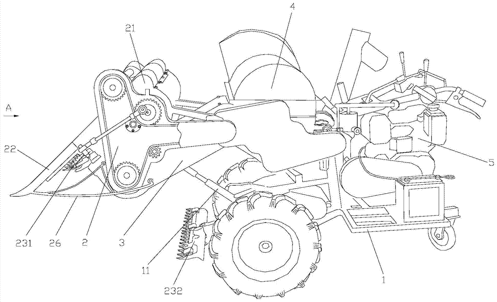
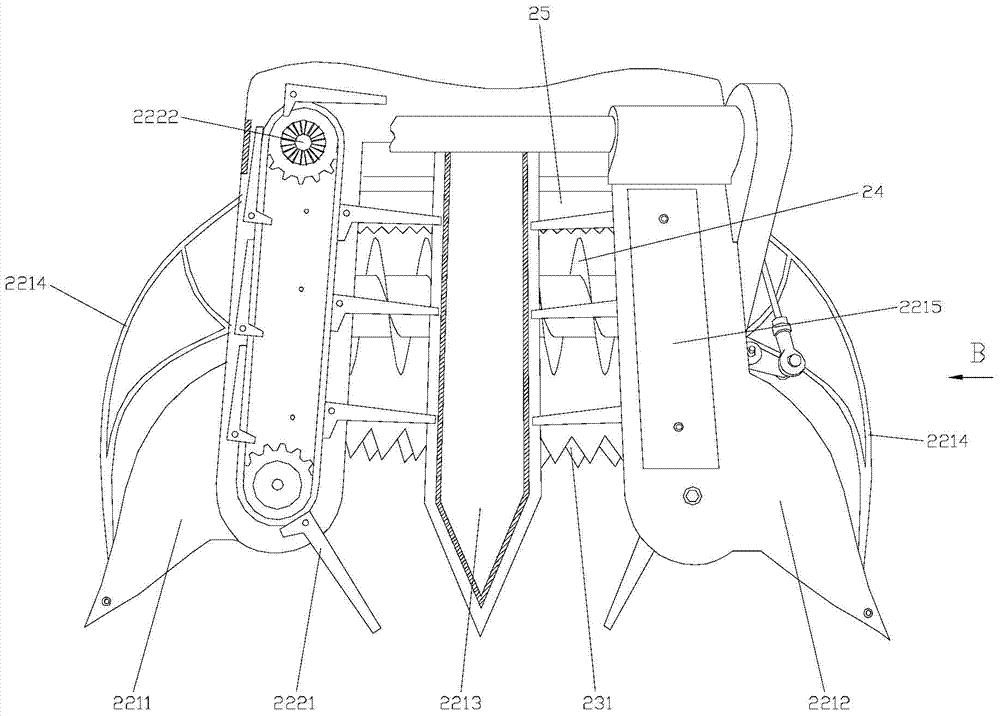
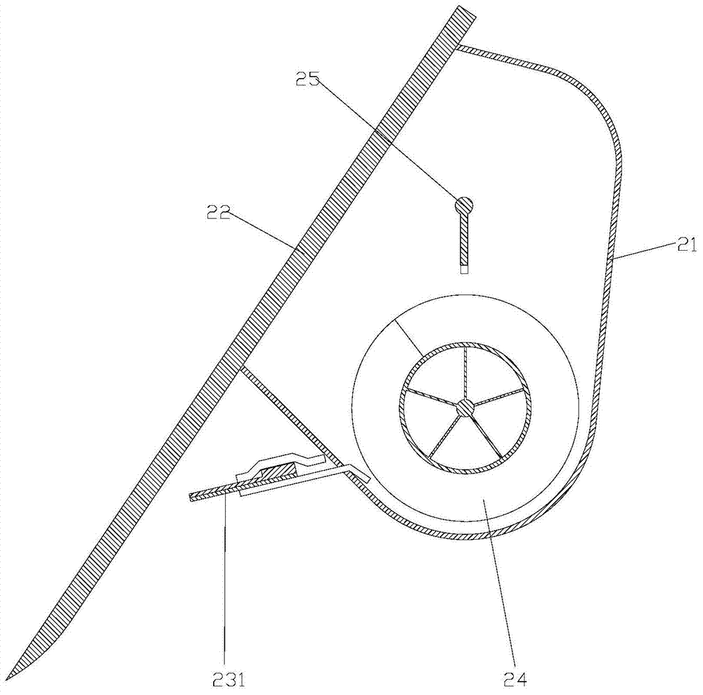
[0023] figure 1 It is a structural schematic diagram of the present invention, figure 2 for figure 1 Partial view of A, image 3 for figure 2 Partial sectional view of B direction, Figure 4 It is a partial sectional view of the grain divider, Figure 5 It is a schematic diagram of the flywheel structure; as shown in the figure: the good combine harvester of the present embodiment includes a walking car body 1, a harvesting part 2, a conveying device 3, a threshing part 4 and an engine 5, and the harvesting part 2 is arranged on The front part of the walking vehicle body 1 includes a bracket shell I21, a grain raising device 22, a cutting edge 23 and a push auger 24, and the grain raising device 22 includes a grain dividing part 221 and a grain raising part 222, and the grain dividing part 221 It is fixedly arranged on the front part of the bracket shell I21 and its upper end is inclined backward. The grain holding part 222 includes a grain holding finger 2221 that can ...


PUM


Abstract

The invention discloses a combined harvester with good power performance. The combined harvester comprises a traveling machine body, a harvesting part, a conveying device, a threshing part and an engine, wherein the harvesting part is disposed on the front portion of the travelling vehicle body and comprises a support shell I, a grain lifter, a cutting edge and a pushing auger; the grain lifter comprises a grain separating part and a grain lifting part, the grain separating part is fixed on the front portion of the support shell I, the upper end of the grain separating part inclines backwardly, and the grain lifting part comprises a grain lifting finger which can slide up and down along the grain separating part; the flywheel of the engine comprises a flywheel body, at least two variable-inertia sliders and an internal balance rotary disc; the variable-inertia sliders are uniformly arranged around the rotary shaft of the flywheel body and are radially and slidably connected to the flywheel body; the internal balance rotary disc serving as a synchronizing device is coaxially and rotatably connected with the flywheel body and is in slide fit with the variable-inertia sliders through a planar slideway; the planar slideway deflects along the circumferential direction of the rotary disc, so that a certain included angle is formed between the planar slideway and the sliding direction of the corresponding slider. The combined harvester with good power performance has the advantages that the grain lifting finger structure driven by a sprocket-chain mechanism is used, the grain lifting finger slides up and down along the grain separating part obliquely disposed on the front portion of the cutting edge and can lift lodging grains and gather the grains so as to cut the grains, cutting missing is reduced, and economical loss is reduced.

Description

technical field [0001] The invention relates to a combine harvester with good power performance, in particular to a combine harvester with good power performance. Background technique [0002] The combine harvester is a harvesting machine that can complete the harvesting, threshing, and removal of sundries of cereal crops at one time, and obtain grains directly from the field. Compared with manual harvesting, it can reduce threshing losses, reduce labor intensity, and save labor. It is indispensable for field operations. of agricultural machinery. [0003] At present, there are small combine harvesters available on the market, which have high production efficiency, low price, flexible and convenient movement, and are suitable for harvesting operations in small fields. In the technology, the front part of the harvesting part is usually provided with a reel for forcing the ears of grain in the working area to the cutting edge. The reel is set higher than the cutting edge, and...

Claims


Application Information

Patent Timeline
Patent Type & Authority Applications(China)
IPC IPC(8): A01D41/00A01D65/02
Inventor 王佳川
Owner 重庆市家创扬帆科技有限公司
Learn More