Liftable stirrer
A mixer and lift-type technology, applied in the field of liftable mixers, can solve the problems of low production efficiency, affect the mixing effect, and cannot mix materials evenly, and achieve the effect of improving work efficiency and shortening mixing time.
- Summary
- Abstract
- Description
- Claims
- Application Information
AI Technical Summary
Problems solved by technology
Method used
Image

Examples
Embodiment Construction
[0009] Specific embodiments of the present invention will be described in detail below in conjunction with the accompanying drawings.
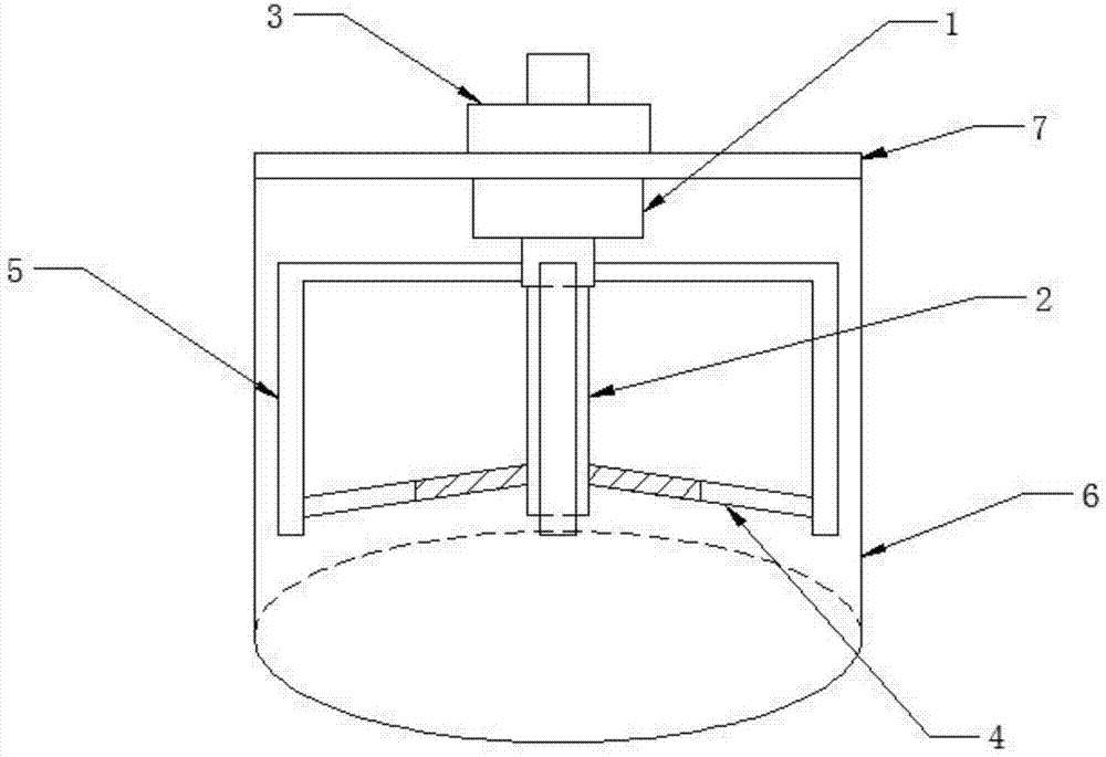
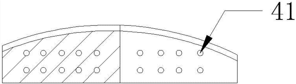
[0010] Such as figure 1 As shown, the mixer is composed of a cylinder body 6 and a stirring part, the rotating pump 2 of the stirring part is installed at the bottom of the driving device 1, and is driven to rotate by the driving device 1; the driving device 1 is also equipped with three fixed arms 5, fixed The arm 5 is also powered by the driving device 1 to make it rotate, and the angular velocity is consistent with the rotation axis 2 . Three agitating blades 4 are hinged on the top of the rotating shaft 2, and the other ends of the agitating blades 4 are respectively hinged on three fixed arms 5. There are blade through holes 41 on the agitating blades 4, through which materials can flow, thereby reducing little resistance. The stirring blade 4 is divided into two parts, wherein the part connected with the rotating shaft 2 is a solid met...
PUM
 Abstract
Description
Claims
Application Information
 - Generate Ideas
- Intellectual Property
- Life Sciences
- Materials
- Tech Scout
- Unparalleled Data Quality
- Higher Quality Content
- 60% Fewer Hallucinations
Browse by: Latest US Patents, China's latest patents, Technical Efficacy Thesaurus, Application Domain, Technology Topic, Popular Technical Reports.
© 2025 PatSnap. All rights reserved.Legal|Privacy policy|Modern Slavery Act Transparency Statement|Sitemap|About US| Contact US: help@patsnap.com