
Extrusion device and extruding machine with same

A technology of extrusion device and extrusion rod, which is applied in the direction of metal extrusion, pressure head/punch rod, metal processing equipment, etc., can solve the problems of cumbersome steps, reduced output, low production efficiency, etc., and achieves convenient use and long service life , the effect of high production efficiency

Inactive Publication Date: 2015-07-01
GUANGZHOU VOCATIONAL COLLEGE OF SCI & TECH
View PDF8 Cites 8 Cited by
  • Summary
  • Abstract
  • Description
  • Claims
  • Application Information

AI Technical Summary

Problems solved by technology

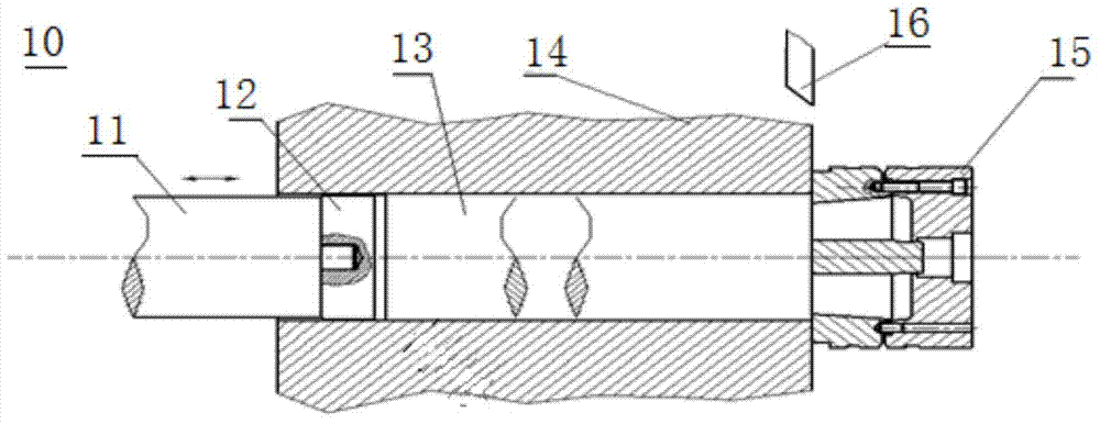
Moreover, the currently used extrusion pad 12 placement method is manual, and the extrusion cycle is long, thereby reducing efficiency, increasing energy consumption and cost
If a mechanical method is used, it will inevitably increase the complexity of the equipment
Therefore, the movable extrusion device 10 is complicated to operate, the steps are cumbersome, waste of manpower, and the production efficiency is low.
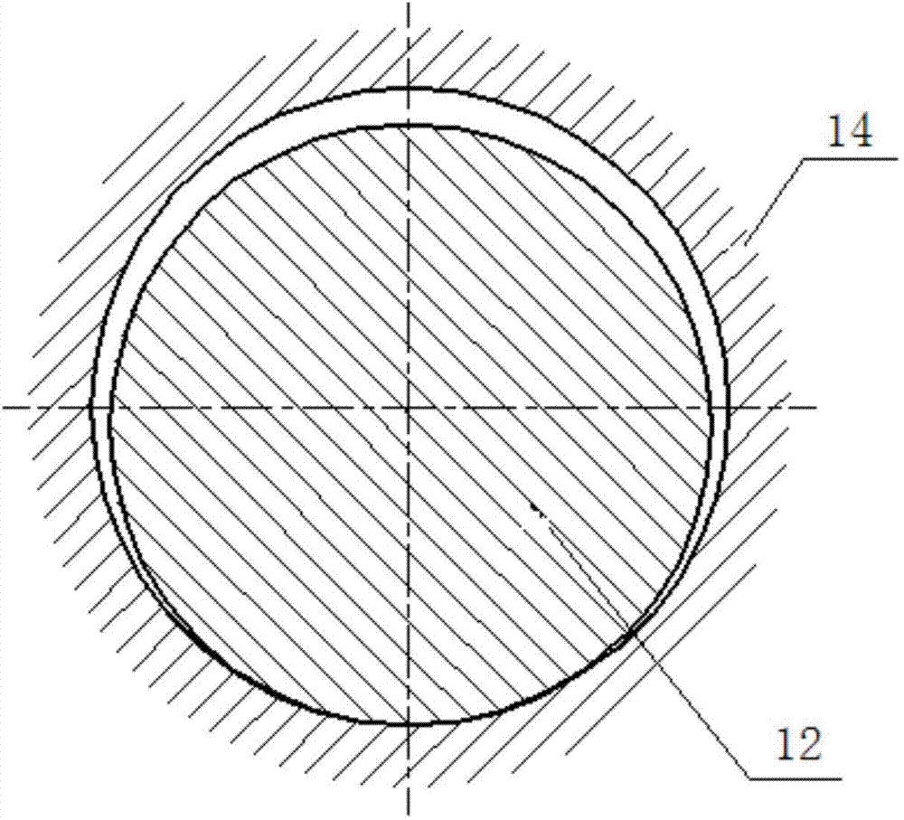
[0008] refer to figure 2 , in the extrusion process, since the extrusion pad 12 is movable, when the extrusion rod 11 is pushed to squeeze the extrusion pad 12, the thrust cannot directly act on the extrusion pad 12, and the extrusion pad 12 cannot Concentric with the extrusion cylinder 14, the gap between the extrusion pad 12 and the extrusion cylinder 14 is uneven, and the upper part of the gap is too large, which will easily lead to the reverse flow of aluminum metal, and the upper part of the extrusion pad 12 will be easily wrapped by aluminum metal , which further leads to the difficulty of separating the extrusion pad 12 from the residual pressure and the premature wear and deformation of the extrusion cylinder, which makes it easy to accumulate impurities on the surface of the aluminum ingot in the extrusion cylinder 14, affecting the quality of the profile and even scrapping it
Therefore, using the movable extrusion device 10, the extrusion cylinder 14 needs to be regularly shut down for cleaning, which reduces the output and increases the labor intensity and production cost.

Method used


Image

  • Extrusion device and extruding machine with same
  • Extrusion device and extruding machine with same
  • Extrusion device and extruding machine with same

Examples


Embodiment Construction

[0033] In order to facilitate the understanding of the present invention, the present invention will be described more fully below with reference to the associated drawings. Preferred embodiments of the invention are shown in the accompanying drawings. However, the present invention can be embodied in many different forms and is not limited to the embodiments described herein. On the contrary, these embodiments are provided to make the understanding of the disclosure of the present invention more thorough and comprehensive.

[0034] It should be noted that when an element is referred to as being “fixed” to another element, it can be directly on the other element or there can also be an intervening element. When an element is referred to as being "connected to" another element, it can be directly connected to the other element or intervening elements may also be present. The terms "vertical," "horizontal," "left," "right," and similar expressions are used herein for purposes ...


PUM


Abstract

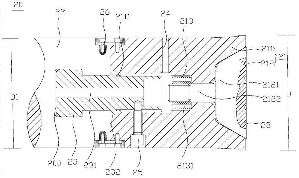
The invention relates to an extrusion device which comprises an extrusion pad, an extrusion rod and a connecting part, wherein the extrusion pad comprises an outer bush and a lining, the outer bush is axially provided with an accommodating hole, the lining is accommodated in the accommodating hole, and the outer bush is connected with the lining; the extrusion rod is axially provided with an inner hole; and one end of the connecting part is cooperated with the inner hole of the extrusion rod, and the other end of the connecting part is connected with the extrusion pad, so that the extrusion pad is fastened with the extrusion rod, and the connecting part and the extrusion rod can move relative to each other along the axial direction. In the extrusion device, the extrusion pad is fixedly connected with the extrusion rod, and therefore, in the process of extrusion, the extrusion rod is always attached to the end face of the extrusion pad; because the connecting part and the extrusion rod can move relative to each other along the axial direction, a situation that the extrusion rod directly transfers a force to the extrusion pad is ensured, and a situation that a force is transferred by the connecting part is avoided, thereby ensuring the service life of the extrusion device; and the extrusion rod drives the extrusion pad to withdraw, so that an aluminium ingot blank is completely separated from the extrusion pad, thereby solving the problem that remnant extruding materials are attached to the extrusion pad and the extrusion pad and an extruding cylinder are non-concentric.

Description

technical field [0001] The invention relates to the technical field of extrusion fittings of aluminum profiles, in particular to an extrusion device and an extrusion machine comprising the extrusion device. Background technique [0002] Modern aluminum profile extrusion technology started late in our country, but since my country's reform and opening up, with the continuous rapid development of my country's economy and the increasing progress of science and technology, my country's aluminum profile extrusion technology has made considerable development and progress, and my country has become a global The largest producer of aluminum profiles. However, compared with developed countries, my country's extrusion technology still has a big gap, mainly reflected in: the extrusion method is too single, the extrusion theory and technology of large-section profiles are immature, and the range of extrudable aluminum alloys is not wide enough. [0003] refer to figure 1 At present, th...

Claims


Application Information

Patent Timeline
Patent Type & Authority Applications(China)
IPC IPC(8): B21C26/00B21C23/21
Inventor 邓汝荣曾蕾
Owner GUANGZHOU VOCATIONAL COLLEGE OF SCI & TECH
Learn More