
Clamping weighing device for car damper

A technology of weighing device and clamping device, applied in static weighing. It can solve the problems that the wheel clamp and the static rail scale cannot be well matched, the depth of the dumper's foundation pit increases, and the investment cost increases, so as to achieve the effect of light weight, compact structure and improved operation efficiency.

Active Publication Date: 2015-07-01
DALIAN HUARUI HEAVY IND GRP CO LTD
View PDF7 Cites 1 Cited by
  • Summary
  • Abstract
  • Description
  • Claims
  • Application Information

AI Technical Summary

Problems solved by technology

[0003] 1. The static rail scale is installed under the dumper, which increases the depth of the foundation pit of the dumper and increases the investment cost; the static rail scale is installed at the entry end of the dumper. Due to the different lengths of the gondola, the wheel gripper and the static rail scale cannot be well matched;
[0004] 2. Since the wheel clamp is set at the entry end of the dumper; the steering machine pulls the whole train to position at the wheel clamp, and clamps the whole train with tipping; if the static track scale is set on the ground, the wheel clamp It can only be placed on the front end of the static rail scale, and a section of heavy truck to be weighed is placed on the static rail scale. Due to the different models of the gondola car, the length difference is relatively large, and the maximum length difference is 2m. It is not fixed, which makes it difficult to pick up the car, and the dumping of the chain dumper affects the overall efficiency;

Method used


Image

  • Clamping weighing device for car damper
  • Clamping weighing device for car damper
  • Clamping weighing device for car damper

Examples


Embodiment Construction

[0023] The present invention will be further described below in conjunction with drawings and embodiments.

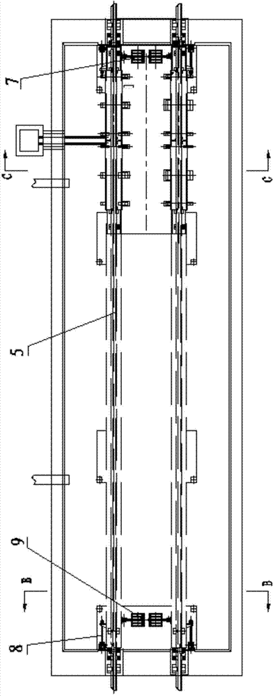
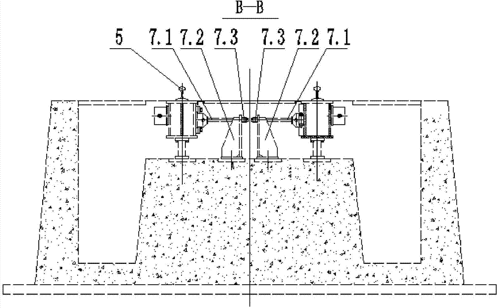
[0024] The embodiment is a clamping and weighing device for a dumper with four transverse tensioning devices 7 and four longitudinal tensioning devices 8 . As shown in the attached picture.

[0025] The clamping and weighing device for the dumper is set on the railway track at the entry end of the dumper. The gondola car first passes through the weighing device and then enters the dumper for dumping. The weighing device includes a platform 1, a pressure sensor 2, a clamping device 4, a lateral Tensioning device 7 and longitudinal tensioning device 8; platform 1 is an integral platform of steel structure, on which platform 1 is provided with running track 5 of a railway gondola car, running track 5 is placed on the track beam of platform 1, and foundation pit is set under platform 1; The pressure sensor 2 is connected to the data processing instrument through a signal l...


PUM


Abstract

The invention discloses a clamping weighing device for a car damper. A weighing device is arranged on a railway rail of a car inlet end of the car damper; the weighing device comprises a platform, a pressure sensor, a clamping device, a cross pulling device and a longitudinal pulling device; a walking rail is placed on ail beams of the platform, and the pressure sensor is mounted between the lower side of the platform and a supporting pier in a foundation pit; the clamping device is installed at one end of the platform; the cross pulling device comprises two groups of pulling mechanisms, wherein every group of pulling mechanism comprises a threaded pull rod, a base and an adjusting nut, and the base is installed above the supporting pier in the foundation pit; one end of the threaded pull rod is connected with the base, and the other end is hinged to two rail beams on the platform; the longitudinal pulling device has the same structure as the cross pulling device; two groups of the longitudinal pulling mechanisms are symmetrically arranged at both sides of the rail beams. The clamping weighing device has the beneficial effects of realizing multi-sectional positioning weighing function, improving running efficiency, and reducing investment; the clamping weighing device is compact in structure, light in weight, low in cost and convenient to maintain; besides, the clamping weighing device is exact in location and high in level of automation.

Description

technical field [0001] The invention belongs to the field of weighing devices for railway locomotives, in particular to static weighing. Background technique [0002] Most of the static weighing devices for railway dumpers in the prior art are static rail scales, and the static rail scales are arranged below the dumper. The weighing method is that after the gondola car enters the dumper, the static rail scale weighs the total weight of the dumper and the heavy vehicle and transmits the parameters to the data processing instrument. The data processing instrument stores the weight of the dumper and the empty car in advance, and the static rail scale transmits The difference between the claimed total weight and the pre-stored dumper and empty weight in the data processing instrument is the weight of the materials dumped in the gondola. The deficiencies in the prior art of this static track scale are: [0003] 1. The static rail scale is installed under the dumper, which incre...

Claims


Application Information

Patent Timeline
IPC IPC(8): B65G67/54B65G67/48G01G19/04
CPCB65G67/48B65G67/54G01G19/04
Inventor 张文海张平徐俊国刘克君
Owner DALIAN HUARUI HEAVY IND GRP CO LTD
Learn More