
Structure for connecting upper and lower parts of bridge wrapped with rubber cap steel tube and constructing method thereof

A technology for connecting structures and rubber caps, applied in the direction of bridges, bridge parts, bridge construction, etc., can solve problems such as limited use range, cracks in main beams and bridge piers, etc., to achieve favorable stress, reduce bending moment value, and improve durability. Effect

Active Publication Date: 2015-07-01
FUZHOU UNIV
View PDF8 Cites 14 Cited by
  • Summary
  • Abstract
  • Description
  • Claims
  • Application Information

AI Technical Summary

Problems solved by technology

However, due to the rigid connection between the upper structure and the lower structure of the continuous rigid frame, flexible piers are required, which greatly limits its application range, especially for the reinforcement and reconstruction of existing simply supported beam bridges.
For simply supported girder bridges using conventional non-flexible piers, transform them into continuous rigid structures. Although expansion devices and supports are eliminated to improve the structural bearing capacity, it is easy to cause cracks in the main girder and bridge piers

Method used


Image

  • Structure for connecting upper and lower parts of bridge wrapped with rubber cap steel tube and constructing method thereof
  • Structure for connecting upper and lower parts of bridge wrapped with rubber cap steel tube and constructing method thereof
  • Structure for connecting upper and lower parts of bridge wrapped with rubber cap steel tube and constructing method thereof

Examples


Embodiment Construction

[0031] The present invention will be further described below in conjunction with the accompanying drawings and specific embodiments.

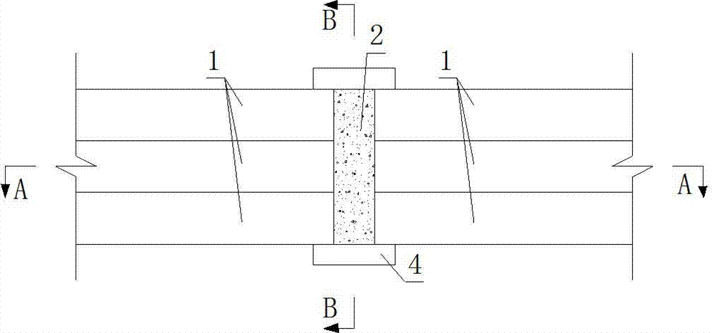
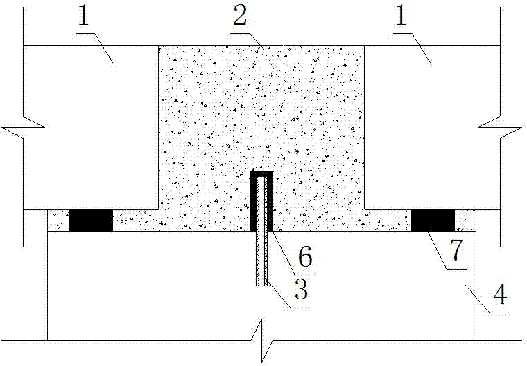
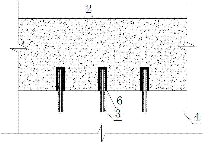
[0032] like Figure 1-10 As shown, a bridge upper and lower connection structure of a rubber-capped steel pipe includes a plurality of piers 4 and abutments 5, and the top surface of the piers 4 or abutments 5 is continuously provided with a plurality of holes 8 at equal intervals along the transverse direction of the bridge. Steel pipes 3 are inserted into the holes 8, rubber caps 6 are placed on the parts of the steel pipes 3 exposed from the holes 8, and the main girder 1 with exposed longitudinal steel bars is placed on the support 7 on the top surface of the pier 4 or abutment 5. Wet joints 2 formed by pouring concrete are filled between the two adjacent girders 1 and the piers 4 or abutments 5, and the reinforcement bars of the wet joints 2 are overlapped with the exposed longitudinal reinforcement bars of the two adjacent girders 1, The...


PUM


Abstract

The invention relates to a structure for connecting upper and lower parts of a bridge wrapped with a rubber cap steel tube. The connecting structure comprises a plurality of piers and abutments, wherein a plurality of holes are consecutively arranged on the tops of the piers or abutments in equal distance along a cross bridge; steel tubes are respectively inserted into the holes, and the parts of the steel tubes exposed out of the holes are wrapped with rubber caps; main girders with exposed longitudinal steel bars are arranged on the bearings at the tops of the piers or abutments, wet joints formed by concrete are filled among said two adjacent main girders and the piers or abutments, the reinforcing steel bars of the wet joints are overlapped with the longitudinal steel bars exposed out of said two adjacent girders, and the bearings at the tops of the piers or abutments are cast in the wet joints. The articulated performance at the connecting position of upper and lower parts of the bridge can be realized by the steel tube and the rubber cap, so that continuous girders have a certain translation and rotation capability at the piers or abutments, the bending moment values of the continuous girders at the connecting position of upper and lower parts are reduced and the stress is more favorable. By adopting the structure, bearings and an expansion device cannot be applied to the bridge, thereby improving the bridge's durability.

Description

technical field [0001] The invention provides an upper and lower connection structure of a steel pipe covered with a rubber cap and a construction method thereof, belonging to the technical field of bridge construction. Background technique [0002] Simply supported girder bridges are statically indeterminate structures. As a common bridge type of small and medium-span bridges, they are widely used in highway bridges in my country because of their simple structure, convenient construction, and low cost. In order to adapt to structural deformation caused by temperature changes and loads, porous simply supported girder bridges usually have expansion joints on each pier (abutment). The jumping caused by the bridge expansion joints and the secondary adverse effects caused by the damage of the expansion joints (such as the additional internal force of the structure, the corrosion of the structure by water leakage, etc.) are often encountered in the actual operation of bridges at ...

Claims


Application Information

Patent Timeline
Patent Type & Authority Applications(China)
IPC IPC(8): E01D19/00E01D21/00
CPCE01D19/00E01D21/00
Inventor 布里斯杰拉 布鲁诺佐丹 托比亚陈宝春薛俊青
Owner FUZHOU UNIV
Learn More