A connection structure of concrete prefabricated beams and steel beams

A technology for connecting structures and concrete, which is applied in the direction of building structure and construction, can solve the problems that the beam does not fully play the role of the full section, hinders the construction of low-carbon, harmonious society, and the separation and equipment layout are inflexible. Uniform and reasonable stress distribution, improved engineering quality, and improved rigidity

Active Publication Date: 2018-08-21
SHANGHAI OPEN STEEL JOIST
View PDF7 Cites 0 Cited by
  • Summary
  • Abstract
  • Description
  • Claims
  • Application Information

AI Technical Summary

Problems solved by technology

[0002] The concrete secondary beams on the floor are usually in the form of hinged connection. The disadvantage of the on-site hinged method is that the bending moment value in the middle of the span, the stress distribution in the beam is uneven, the middle is large, and the two sides are small, and the beam does not fully play the role of the full section; the stiffness of the hinged connection The value is small, and the mid-span deflection is large; at the same time, on-site operations require a lot of labor and the construction period is long. With the continuous rise of labor costs, the traditional extensive construction technology mainly based on on-site operations has seriously hindered low-carbon, harmonious construction. social construction
[0003] Structurally, for traditional concrete building structures, when the span is large, the beam height and reinforcement will increase accordingly; when the beam height is limited, the bottom column network is usually not very large, and the interior of a building with more columns is separated Inflexible to equipment arrangement, relatively poor in modifiability and usability

Method used


Image

  • A connection structure of concrete prefabricated beams and steel beams
  • A connection structure of concrete prefabricated beams and steel beams
  • A connection structure of concrete prefabricated beams and steel beams

Examples


Embodiment Construction

[0016] In order to make the technical means, creative features, achieving goals and effects of this utility easy to understand, the following is combined with specific illustrations to further explain this utility.

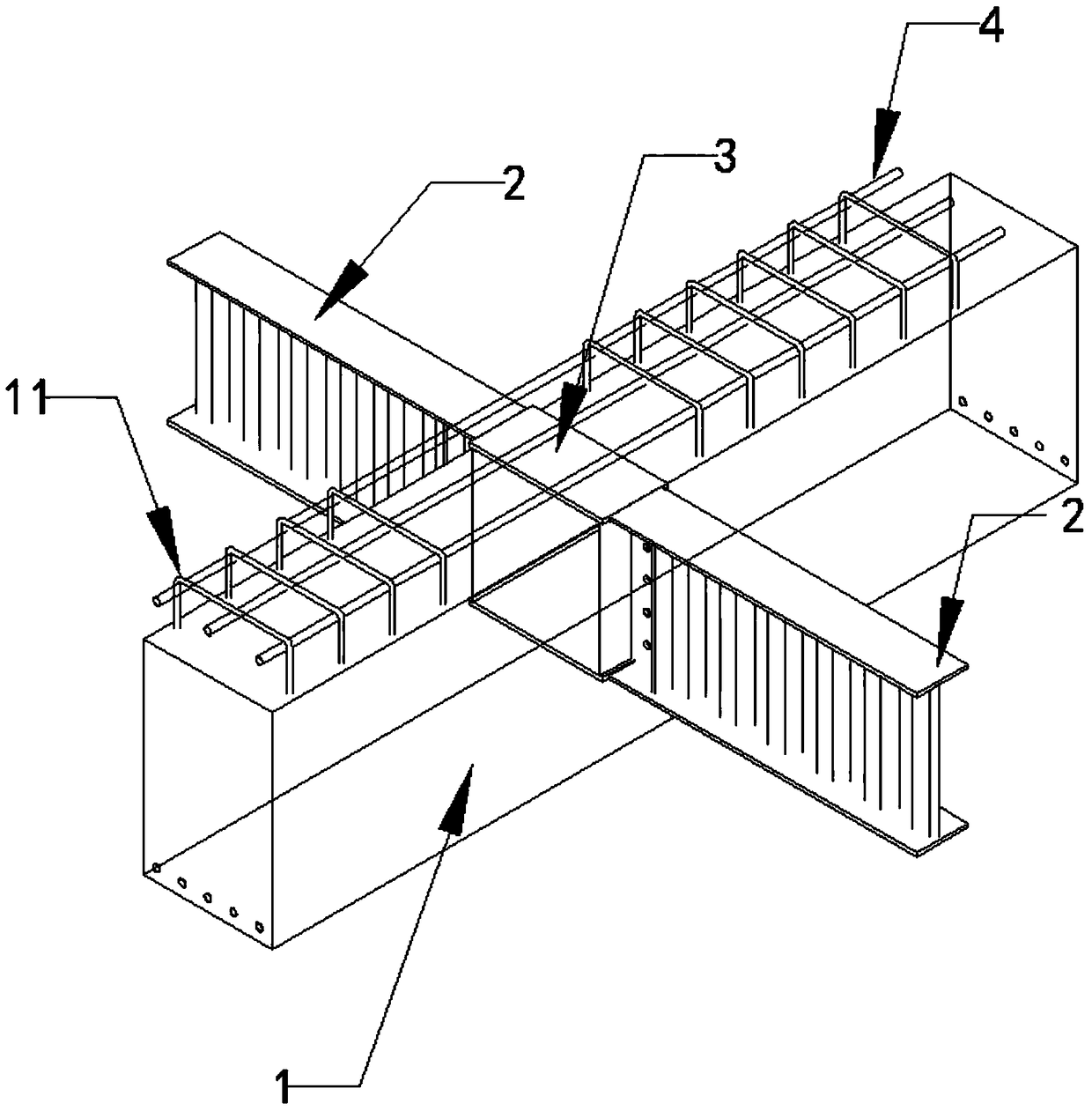
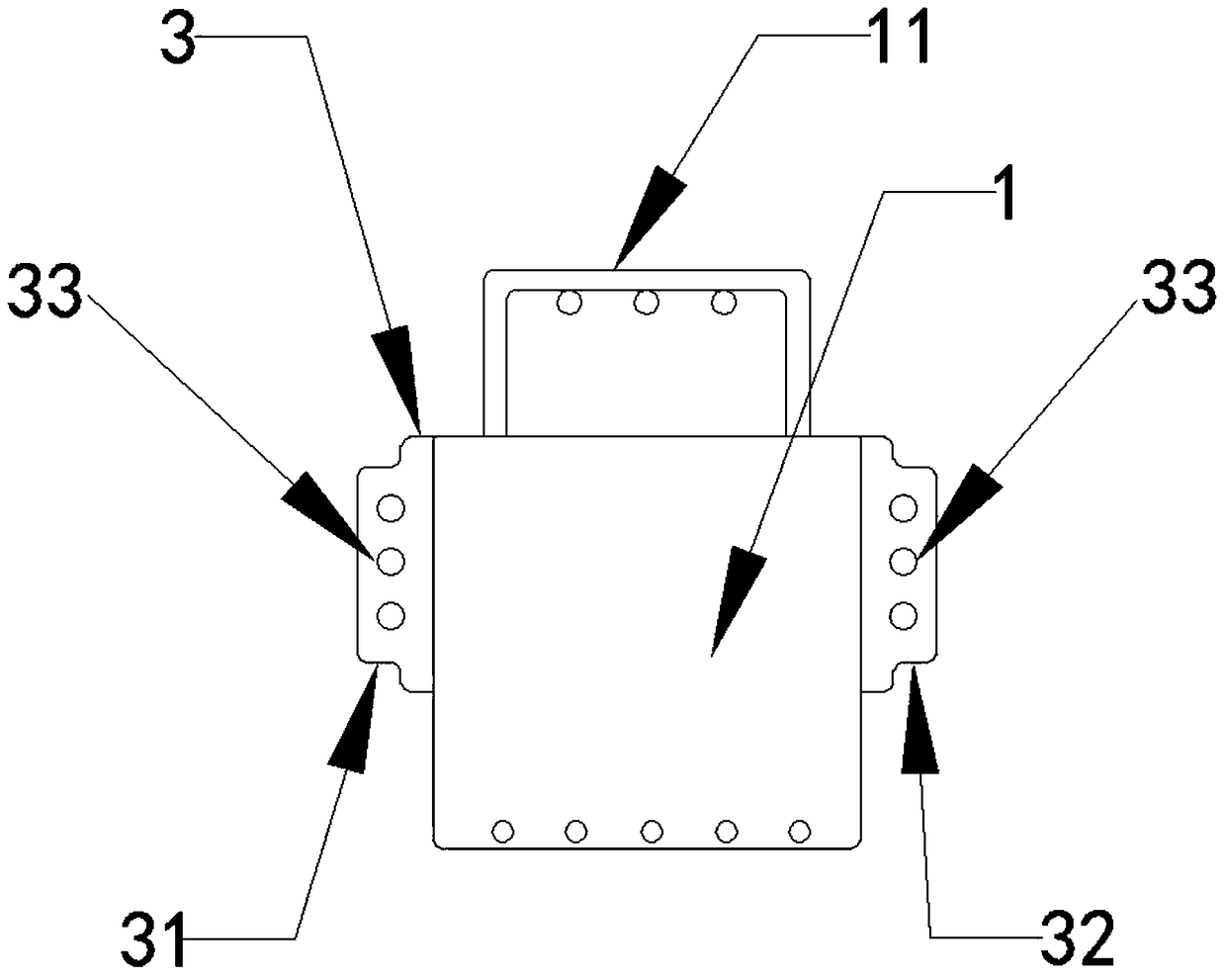
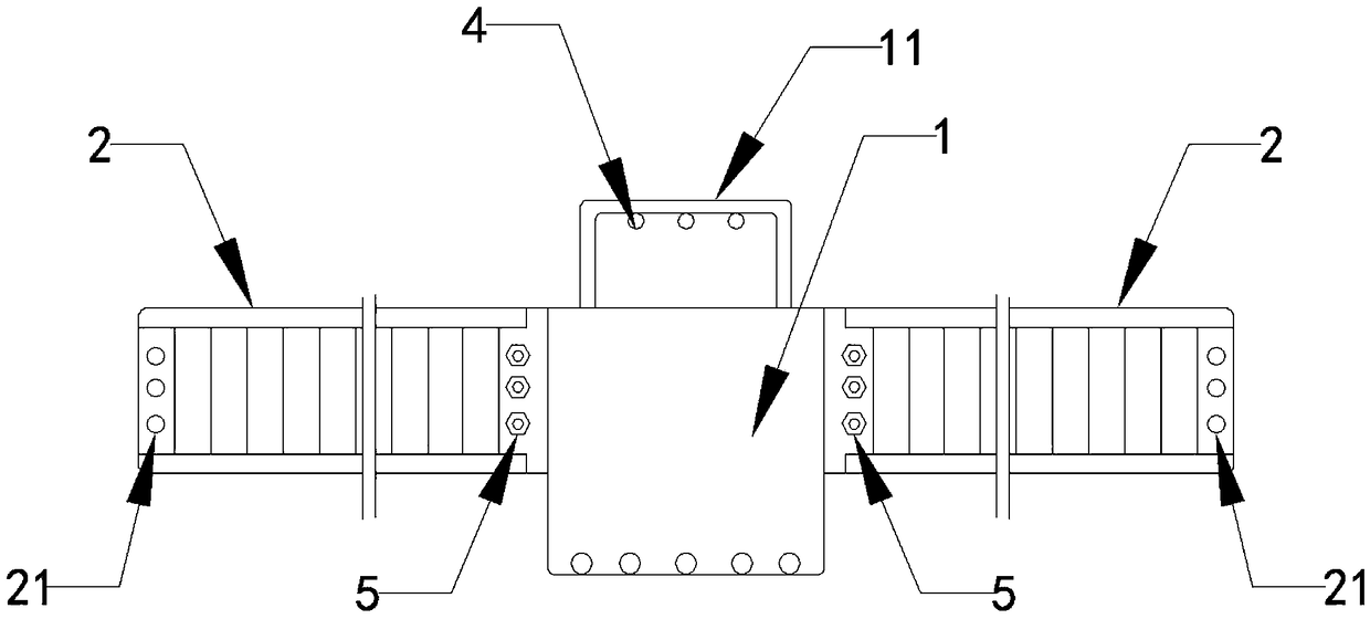
[0017] See Figure 1-3 , A connection structure of precast concrete beams and steel beams, which includes a precast concrete composite beam 1 and a factory prefabricated steel structure beam 2. The concrete composite beam 1 is installed between adjacent main beams and ends It is fixed to the main beam by node connectors. The embedded part 3 is provided on the body in the extension direction of the concrete composite beam 1. The embedded part 3 is formed to extend to the outside of the concrete composite beam 1 and is used for fixing the steel structure beam 1 in place The connecting plate Ⅰ31, the connecting plate Ⅱ32, the connecting plate Ⅰ31 and the connecting plate Ⅱ32 are symmetrically arranged on both sides of the extension direction of the concrete composite be...


PUM


Abstract

The invention relates to a concrete precast beam and girder connecting structure comprising a concrete superposed beam and a steel structure beam; the concrete superposed beam is arranged between adjacent main beams; the body of the concrete superposed beam in an extension direction is provided with an imbed part; the imbed part is provided with a connecting board extending to the outer side of the concrete superposed beam and used for fixing and locating the steel structure beam; the connecting board is provided with a bolt hole I; two ends of the steel structure beam are respectively provided with a bolt hole II; high intensity bolts between the bolt hole I and bolt holes II can fix the concrete superposed beam with the steel structure beam so as to form a cross intersect structure; the beneficial effects are that nodes are fastened by high intensity bolts, steel structure beam wing edges are connected through welding lines, so the prefabricated girder can form a continuous beam structure form, thus obviously improving structure and nodes rigidity, and node connecting structure can realize fully rigid connection.

Description

Technical field [0001] The invention relates to the field of industrial and civil construction, in particular to a connection structure of a precast concrete beam and a steel beam. Background technique [0002] Floor concrete secondary beams are usually articulated connections. The disadvantages of on-site articulation are the mid-span bending moment value, uneven internal stress distribution of the beam, large middle and small sides, and the beam does not fully play the role of the full section; the rigidity of the articulated connection The value is small and the mid-span deflection is large. At the same time, on-site operations require a lot of labor and a long construction period. With the continuous increase of labor costs, the traditional extensive construction technology based on on-site operations has seriously hindered low-carbon and harmonious Social construction. [0003] In terms of structure, in traditional concrete building structures, when the span is large, the bea...

Claims


Application Information

Patent Timeline
Patent Type & Authority Patents(China)
IPC IPC(8): E04B1/58E04B1/41
CPCE04B1/41E04B1/58E04B1/5812E04B1/5831
Inventor 陈明
Owner SHANGHAI OPEN STEEL JOIST
Why Eureka
Try Eureka