Rotary fall type flush toilet

A toilet and swivel-type technology, which is applied in flush toilets, water supply devices, buildings, etc., to achieve the effects of rapid drainage, enlarged flushing area, and concentrated water flow

Inactive Publication Date: 2015-07-01
TANGSHAN MONOPY CERAMIC
View PDF7 Cites 2 Cited by
  • Summary
  • Abstract
  • Description
  • Claims
  • Application Information

AI Technical Summary

Problems solved by technology

[0004] The present invention aims to solve the above-mentioned problems existing in the existing flushing toilets, and provides a spin-down flushing system that can increase the pressure during flushing, ensure that the water flow can form a rotation on the surface of the pot cavity, and achieve clean flushing and good sewage discharge effect Toilet

Method used


Image

  • Rotary fall type flush toilet
  • Rotary fall type flush toilet
  • Rotary fall type flush toilet

Examples


Embodiment Construction

[0020] The present invention is described in detail below through examples, and the purpose is only to better understand the contents of the present invention. Therefore, the examples given are not intended to limit the content of the present invention.

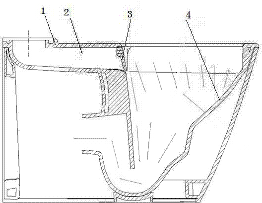
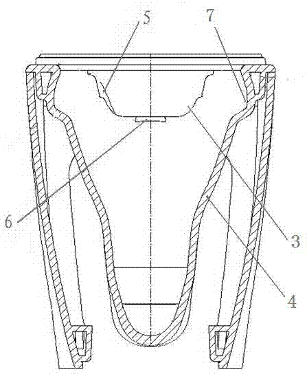
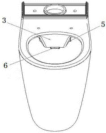
[0021] Referring to the accompanying drawings, the toilet main body 1 is the supporting body of the pot body 4 and the water tank. The inside of the toilet main body 1 is provided with a main water channel 2 connected to the water tank at the position above the rear end. The main water channel 2 is connected with the pot in the toilet main body 1 The inner cavity of the body 4 is connected with a water diversion plate 3, and three gaps are formed between the water diversion plate 3 and the surface of the pot body 4, that is, the gap 5 on both sides and the gap 6 at the bottom, wherein the cross-sectional area of ​​the gap 5 on both sides is 1800 ~2300 square millimeters, the cross-sectional area of ​​the bottom gap 6 is 2300~...


PUM


Abstract

The invention relates to flush toilets, particularly to a rotary fall type flush toilet. The rotary fall type flush toilet comprises a toilet main body; a main water channel which is connected with a water tank is formed inside the toilet main body; the communication position of the main water channel and an inner chamber of a pot body which is formed in the toilet main body is provided with a water diversion plate; bilateral gaps and a bottom gap are formed between the water diversion plate and the surface of the pot body; the inner edge of an upper opening of the pot body is provided with a concaved water guide groove; the water flow from the bilateral gaps passes through the water guide groove to flush the surface of the pot body in a rotating mode to flow towards the bottom of the pot body; the water flow from the bottom gap directly flushes the surface of the rear side of the pot body to directly flow towards the bottom of the pot body. According to the rotary fall type flush toilet, the mode that the pot body is flushed through a plurality of large and small holes formed below a water ring of the conventional toilet is cancelled, the effect on the rotary flushing on the pot body is achieved through the diversion of the water diversion plate due to the main water channel which is formed above the toilet, the gaps are small, and accordingly the flushing pressure is large and dirties and stains adhesive to the surface of the pot body can be greatly flushed.

Description

technical field [0001] The invention relates to a flush toilet, in particular to a swivel flush toilet. Background technique [0002] Current flushing toilets, such as a water-saving flush-down toilet disclosed in CN201120311958, generally use rings to flush the surface of the pot body through the water ring and the large and small holes in the lower part of the water ring to achieve the effect of sewage discharge. However, due to the insufficient flushing pressure of this method, the water flow is too scattered and not concentrated during flushing, and the flushing force is not enough, and the water flow is difficult to form a rotation on the surface of the pot body, leaving a dead angle for flushing, resulting in easy residues of dirt on the surface of the pot body. Causes dirty washing. [0003] CN201020112131 discloses a wash-down toilet. Although the previous method of rinsing the surface of the pot body through the scouring holes in the lower part of the water ring ha...

Claims


Application Information

Patent Timeline
IPC IPC(8): E03D11/08
CPCE03D11/08
Inventor 李树元孙仕良郭金健关义明寿志满吕艳茶黄建峰佟双喜马爱军王瑞雪张刚孙秋杰王银环董珊珊
Owner TANGSHAN MONOPY CERAMIC
Why Eureka
Try Eureka