Vertical single-stage torque flow pump

A swirl pump, single-stage technology, applied in the field of vertical single-stage swirl pumps, can solve problems such as head drop, failure to meet fire pump standards, pump volume increase, etc., and achieve the effect of large head

Inactive Publication Date: 2015-07-01
JOHNSON PRECISION ENG SUZHOU
View PDF5 Cites 0 Cited by
  • Summary
  • Abstract
  • Description
  • Claims
  • Application Information

AI Technical Summary

Problems solved by technology

[0003] 1. In order to obtain a larger head, the existing vertical single-stage pump can only rely on the diameter of the impeller to increase, resulting in an increase in pump volume;
[0004] 2. After long-term operation, the seal ring of th

Method used


Image

  • Vertical single-stage torque flow pump

Examples


Example Embodiment

[0013] The present invention will be further described below in conjunction with the drawings and embodiments of the specification.

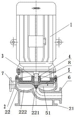
[0014] Such as figure 1 As shown, the vertical single-stage swirl pump includes a motor 1, a pump body 2, a rotating shaft 3, a pump cover 4, and an impeller 5. The lower part of the pump body is a support seat 21, and the upper part of the support seat is a flow channel partition 22. The cover 4 is arranged in the pump body and above the flow passage partition plate, thereby forming a pressing-out chamber 5 between the pump cover and the flow passage partition plate; the motor is arranged longitudinally at the upper end of the pump body, and the rotating shaft 3 is longitudinally arranged in the pump body. The output shaft is connected with the rotating shaft, one end of the rotating shaft passes through the pump cover into the extrusion chamber, and the impeller 5 is fixedly connected with the end of the rotating shaft in the extrusion chamber; t...


PUM

PropertyMeasurementUnit
Depthaaaaaaaaaa

Abstract

The invention relates to a vertical single-stage torque flow pump which comprises a motor, a pump body, a rotating shaft, a pump cover and an impeller. A supporting base is arranged at the lower portion of the pump body. A channel partition plate is arranged above the supporting base. The pump cover is arranged in the pump body and located above the channel partition plate so that a press-out chamber can be formed. The motor is longitudinally arranged at the upper end of the pump body. The rotating shaft is longitudinally arranged in the pump body. The motor is connected with the rotating shaft. One end of the rotating shaft penetrates through the pump cover and enters the press-out chamber. The impeller is fixedly connected with the end, located in the press-out chamber, of the rotating shaft. The impeller comprises a rotating center connected with the rotating shaft and a plurality of blades evenly distributed around the rotating center. Gaps are formed between the lower side edges of the blades and the upper side face of the channel partition plate. No sealing element needs to be installed between the impeller and the pump body, and the problem that an existing vertical single-stage pump is low in efficiency when a sealing element is abraded does not exist; on the premise of not increasing the overall size of the pump body, compared with the existing vertical single-stage pump, the vertical single-stage torque flow pump has the advantages that the stroke is larger and can not be decreased even when flow is increased.

Description

technical field [0001] The invention relates to the field of vertical single-stage pumps, in particular to a vertical single-stage swirl pump. Background technique [0002] The existing vertical single-stage pump adopts a centrifugal pump structure, and there is a running gap between the high and low pressure chambers in the pump, that is, the matching gap between the pump body and the impeller. In order to ensure the working efficiency of the centrifugal pump, the above gap is realized by a sealing ring Sealed, it has the following disadvantages: [0003] 1. In order to obtain a larger head, the existing vertical single-stage pump can only rely on the diameter of the impeller to increase, resulting in an increase in pump volume; [0004] 2. After long-term operation, the seal ring of the pump will wear out rapidly, resulting in a decrease in pump performance; [0005] 3. Most of the centrifugal pumps, as the flow rate increases, the head continues to drop rapidly, which c...

Claims


Application Information

Patent Timeline
IPC IPC(8): F04D13/06F04D29/42F04D29/22
CPCF04D13/06F04D29/22F04D29/426
Inventor 孙跃林施长岗王成
Owner JOHNSON PRECISION ENG SUZHOU
Why Eureka
Try Eureka