Industrial water cooling device

A cold water device, industrial technology, applied in the direction of household refrigeration devices, lighting and heating equipment, household appliances, etc., can solve the problems of high failure rate, high cost, complex structure, etc., and achieve low environmental pollution, low purchase and use costs, The effect of large heat exchange area

Inactive Publication Date: 2013-07-24
ACADEMY OF ARMORED FORCES ENG PLA
View PDF7 Cites 10 Cited by
  • Summary
  • Abstract
  • Description
  • Claims
  • Application Information

AI Technical Summary

Problems solved by technology

[0005] In order to solve the defects of complex structure, high failure rate and high cost of the existing industrial chiller system, the present invention proposes an industrial chiller, comprising: a water tank (1), a self-priming pipeline pump (13), and a water outlet station (10) , backwater station (9), radiator (5), air blower (8), it is characterized in that, the water inlet of described self-priming pipeline pump (13) connects with described water tank (1) through water outlet hose (14) connection, the water outlet is connected to the outlet water station (10) through a connecting pipe (12), and water is supplied to the outside; hot water is collected by the return water station (9), and the water inlet of the radiator (5) is connected to The hose (7) is connected to the return water station (9), its water outlet is connected to the water tank (1) through the return hose (2), and the blower (8) is connected to the radiator (5) To supply air to the radiator, the hot water entering the return water station (9) is radiated and cooled by the radiator (5) with the assistance of the blower (8), and flows back to the water tank (1 ) to complete a cycle

Method used


Image

  • Industrial water cooling device
  • Industrial water cooling device
  • Industrial water cooling device

Examples


Embodiment Construction

[0018] Industrial chillers are usually divided into water-cooled and air-cooled. The air-cooled chiller uses air as the medium of heat exchange, and the heat is taken away through the air. Compared with water-cooled chillers, air-cooled chillers do not need to install cooling towers, are suitable for water shortage conditions, and are easy to install and move. The industrial cold water device of the present invention belongs to the air-cooled type.

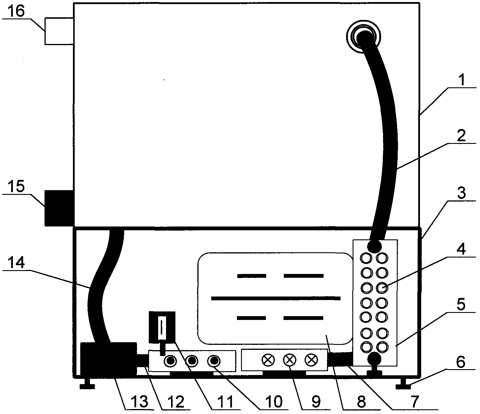
[0019] Such as figure 1 As shown, the industrial cold water device of the present invention includes: a water tank 1, a radiator 5, a blower 8, a return water station 9, a water outlet station 10, a water temperature and pressure gauge 11, and a self-priming pipeline pump 13. The water inlet of the self-priming pipeline pump (13) is connected to the water tank (1) through a water outlet hose (14), and the water outlet of the water pump is connected to the water outlet station (10) through a connecting pipe (12) to supply water t...


PUM


Abstract

The invention discloses an industrial water cooling device which mainly comprises a water tank 1, a self-sucking pipeline pump 13, a water discharging station 10, a water temperature and water pressure meter 11, a water return station 9, a heat radiator 5 and a blower 8, wherein a water inlet of the self-sucking pipeline pump 13 is connected with the water tank 1 through a water discharging hose 14; a water outlet of a water pump is connected with the water discharging station 10 through a connecting pipe 12; and the water discharging station is used for providing cooling water with enough pressure and proper temperature to a plurality of equipment. After the cooling water flows through the equipment to take away heat, the water temperature is increased, hot water is gathered through the water return station 9 and is introduced into a heat radiator 5 through a connecting hose 7; the hot water flows through heat radiating fin tubes which are distributed in a S-shaped manner in the heat radiator and is assisted by the blower 8 to dissipate and cool; and the cold water obtained by cooling flows out of a water outlet of the heat radiator 5 and flows back to the water tank 1 through a water return hose 2 to finish one circulation. The industrial water cooling device does not need a refrigerant circulating system for cooling circulating water in the prior part and has the characteristics of low power consumption, high capacity, easiness in operation, simplicity, high efficiency, safety, reliability and the like.

Description

technical field [0001] The invention belongs to the technical field of circulating water cooling devices for industrial devices, and in particular relates to a simple and efficient industrial cooling device. Background technique [0002] In modern industrial production, high-speed rotating spindles or high-energy conversion devices in laser processing equipment, welding equipment, milling machine tools, injection molding equipment, electroplating equipment and other equipment will generate a lot of heat. In order to ensure the safe and stable operation of these industrial equipment, Circulating water is often used for cooling, which gave birth to the development of industrial chillers. [0003] The function of the industrial chiller is mainly to reduce the temperature of the cooling water to a constant value according to the operation requirements of the equipment and provide it to the cooling heat exchange system of the cooled equipment, take away the heat of the cooled equ...

Claims


Application Information

Patent Timeline
Patent Type & Authority Applications(China)
IPC IPC(8): F25D1/00
Inventor 王海斗徐滨士马国政张森杨大祥
Owner ACADEMY OF ARMORED FORCES ENG PLA
Why Eureka
Try Eureka