Differential Transformer Displacement Sensor

A differential transformer type, displacement sensor technology, applied in the field of sensors, can solve the problems of poor linearity and low accuracy of differential transformer type displacement sensors, improve linearity and output accuracy, increase linear travel, and improve magnetic field distribution. Effect

Inactive Publication Date: 2018-02-23
LANZHOU UNIVERSITY OF TECHNOLOGY
View PDF9 Cites 2 Cited by
  • Summary
  • Abstract
  • Description
  • Claims
  • Application Information

AI Technical Summary

Problems solved by technology

[0003] In order to solve the problem of poor linearity and low precision of the differential transformer displacement sensor, the present invention proposes a differential transformer displacement sensor to improve the linearity and precision of the differential transformer displacement sensor

Method used


Image

  • Differential Transformer Displacement Sensor
  • Differential Transformer Displacement Sensor
  • Differential Transformer Displacement Sensor

Examples


Embodiment 1

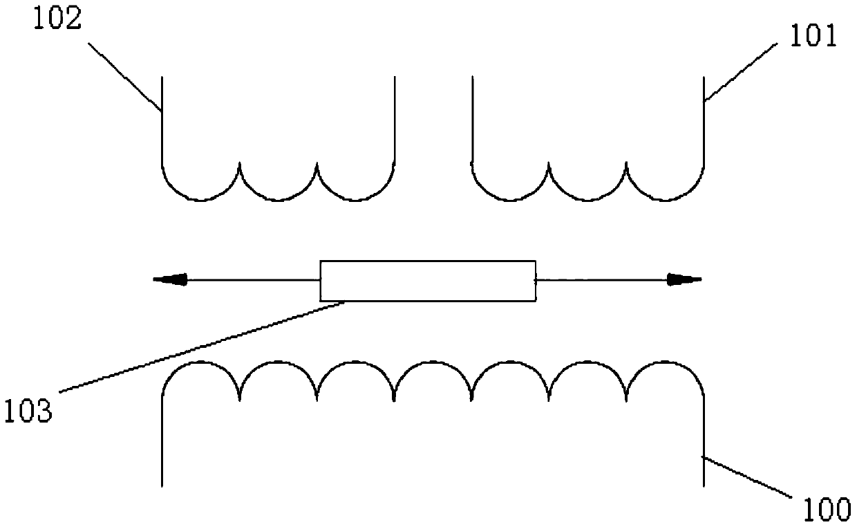
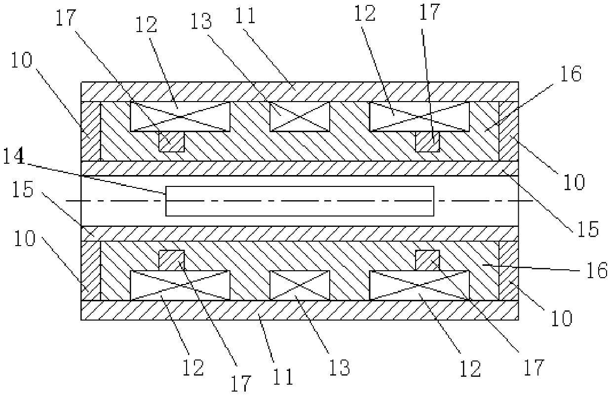
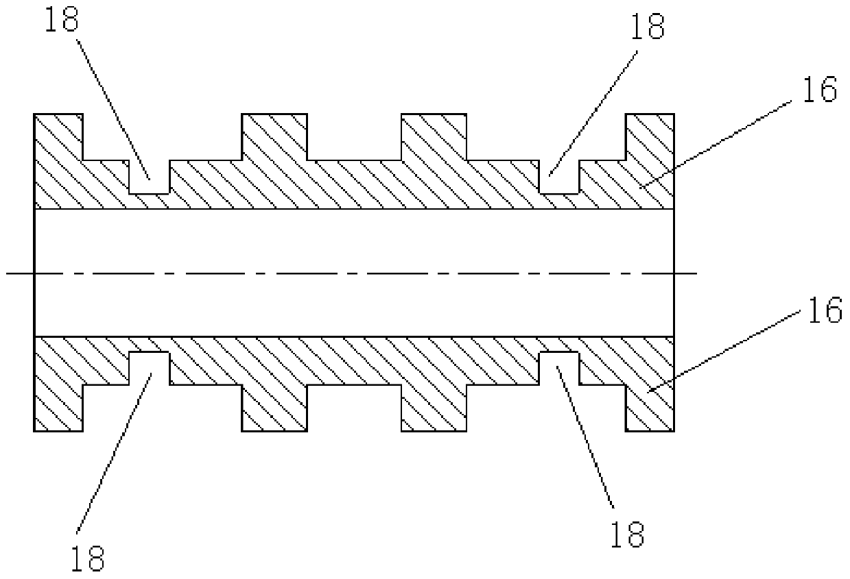
[0038] Such as figure 2 and image 3 As shown, the differential transformer displacement sensor of this embodiment includes a skeleton 16 , an annular end cover 10 , a casing 11 , an iron core 14 , two secondary coils 12 , a primary coil 13 , a pressure-resistant tube 15 and a magnetically permeable ring 17 . The skeleton 16 is a cylindrical structure, the outer wall of the skeleton 16 is provided with a primary coil groove and two secondary coil grooves, and the two secondary coil grooves are symmetrically arranged on both sides of the primary coil groove, and the primary coil 13 is wound around The secondary coil 12 is disposed in the groove of the primary coil, and the secondary coil 12 is wound in the groove of the secondary coil. The shell 11 is sheathed on the framework 16 , and both ends of the framework 16 are provided with ring-shaped end caps 10 . The iron core 14 is located in the inner cavity of the skeleton 16 . The skeleton 16 is provided with an annular groo...

Embodiment 2

[0040] Such as Figure 4 and Figure 5 As shown, the differential transformer type displacement sensor of this embodiment includes an annular end cover 20 , a casing 21 , an iron core 24 , two secondary coils 22 , three primary coils 23 , a skeleton 25 and a magnetically permeable ring 26 . The skeleton 25 is a cylindrical structure, the secondary coil 22 and the primary coil 23 are wound on the skeleton 25 , and the secondary coil 22 is located between two adjacent primary coils 23 . The casing 21 is sheathed on the frame 25 and covers the primary coil 23 and the secondary coil 22 , and both ends of the frame 16 are provided with ring-shaped end caps 20 . The iron core 24 is located in the inner cavity of the skeleton 25 . An annular groove 27 is provided on the outer wall of the skeleton 25 , the annular groove 27 is coaxial with the skeleton 25 , and the magnetically conductive ring 26 is installed in the annular groove 27 . Wherein, the number of the annular slots 27 is...

Embodiment 3

[0042] Such as Figure 6 and Figure 7 As shown, the differential transformer displacement sensor of this embodiment includes an annular end cover 30 , an iron core 34 , a primary coil 32 , two secondary coils 33 , a casing 31 , a frame 35 and a magnetically permeable ring 36 . The skeleton 35 is a cylindrical structure, the primary coil 32 is wound on the skeleton 35, the secondary coil 33 is wound on the outer periphery of the primary coil 32, the shell 31 is sleeved on the skeleton 35, and covers the primary coil 32 and the secondary coil 33, and both ends of the framework 35 are provided with ring-shaped end caps 30. The iron core 34 is located in the inner cavity of the skeleton 35 . The outer wall of the skeleton 35 is provided with an annular groove 37 , which is coaxial with the skeleton 35 , and the magnetically conductive ring 36 is installed in the annular groove 37 . As shown in the figure, the number of annular grooves 37 is two.


PUM


Abstract

The invention belongs to the technical field of sensors. In order to solve the problem of poor linearity and low precision of the differential transformer displacement sensor, the present invention proposes a differential transformer displacement sensor, which includes a primary coil, a secondary coil and a skeleton, the skeleton is a cylindrical structure, the The primary coil and the secondary coil are wound on the skeleton, and the magnetizer is arranged on the skeleton, and the magnetizer is symmetrical with respect to the central axis of the skeleton. When the iron core of the differential transformer-type displacement sensor of the present invention moves toward the direction close to the secondary coil, the magnetic conductor will greatly increase the magnetic flux passing through the secondary coil, thereby improving the magnetic field distribution in the differential transformer-type displacement sensor, so that The magnetic field distribution in the differential transformer displacement sensor is more uniform, which ensures that the sum of the magnetic flux increments of multiple secondary coils changes approximately linearly, thereby improving the linearity and output accuracy of the differential transformer displacement sensor and increasing its linearity. journey.

Description

technical field [0001] The invention belongs to the technical field of sensors, and in particular relates to a differential transformer type displacement sensor. Background technique [0002] The differential transformer displacement sensor is a displacement sensor that works on the principle of electromagnetic induction. figure 1 It is a schematic diagram of the working principle of the differential transformer displacement sensor, such as figure 1 As shown, the differential transformer displacement sensor includes a primary coil 100 , a first secondary coil 101 , a second secondary coil 102 and an iron core 103 . During the working process of the differential transformer type displacement sensor, when the iron core 103 moves to one side of the first secondary coil 101, the mutual inductance between the primary coil 100 and the first secondary coil 101 increases, and the first secondary coil 101 generates The mutual inductance electromotive force V1 increases, and at the ...

Claims


Application Information

Patent Timeline
Patent Type & Authority Patents(China)
IPC IPC(8): G01B7/02
Inventor 冀宏李瑞锋胡启辉王静李小平苏玛亮解浩赵继国
Owner LANZHOU UNIVERSITY OF TECHNOLOGY
Why Eureka
Try Eureka