Magnetic shoe magnetizing device

A technology of magnetizing device and magnetic tile, applied in electromechanical devices, magnetic objects, electrical components, etc., can solve the problems of low precision, low processing efficiency, and poor flow rigidity of tooling

Inactive Publication Date: 2019-04-26
杭州异客科技有限公司
View PDF3 Cites 5 Cited by
  • Summary
  • Abstract
  • Description
  • Claims
  • Application Information

AI Technical Summary

Problems solved by technology

[0003] The deficiencies of the existing equipment are: 1. The tooling has poor flow stiffness and low processing efficiency; 2. The magnetic tiles are loaded slowly, with low precision, and are prone to errors; 3. The shrapnel is difficult to clamp and load; 4. Th...

Method used


Image

  • Magnetic shoe magnetizing device
  • Magnetic shoe magnetizing device
  • Magnetic shoe magnetizing device

Examples


Embodiment Construction

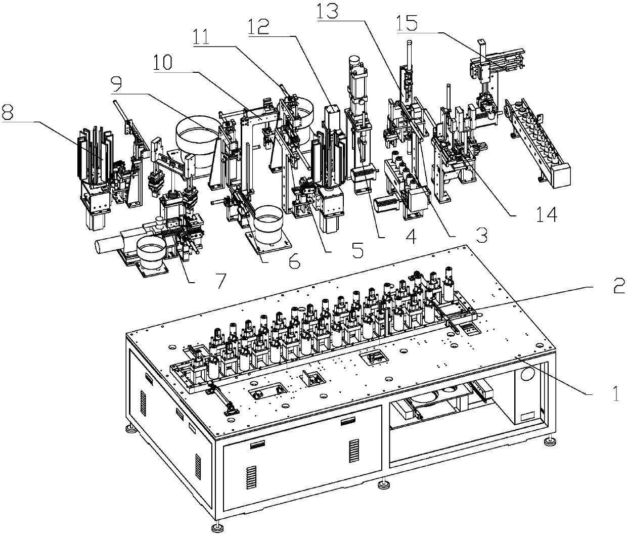
[0036] Such as figure 1As shown, the described automatic assembly equipment for micro DC motors is characterized in that it includes a frame (1), a tooling circulation device (2) installed on the frame (1), and a casing feeding device (3) , Shell riveting device (4), first magnetic tile feeding device (5), shrapnel feeding device (6), ground wire welding device (7), second magnetic tile feeding device (8), bearing pressure Spring feeding device (9), casing transfer device (10), bearing feeding device (11), magnetic tile pressing device (12), magnetic tile magnetizing device (13), glue coating device (14) and The finished product unloading device (15); the tooling circulation device (2) is installed in the center of the casing feeding device (3), and is used for placing and transporting the casing to be assembled, and a mobile unit of the tooling circulation device (2) has Two different fixtures, one mobile unit has only one casing; the casing feeding device (3) is located nex...


PUM


Abstract

The invention relates to the field of motor assembly, in particular to assembly equipment of a minitype direct current motor, and provides a magnetic shoe magnetizing device. The magnetic shoe magnetizing device comprises a second magnetic shoe carrying mechanism, a magnetizing assembly, a machine shell placing assembly and a machine shell compaction assembly; carrying of a machine shell between atool circulating device and the magnetizing assembly is realized through the second magnetic shoe carrying mechanism; the machine shell compaction assembly is mounted above the magnetizing assembly,the machine shell placing assembly is mounted below the magnetizing assembly, and the machine shell compaction assembly, the magnetizing assembly and the machine shell placing assembly are located ona same vertical axis line; the magnetizing assembly comprises an eleventh mounting seat, a magnetizing bag and an induction coil; and the magnetizing bag and the induction coil are mounted on the eleventh mounting seat, and the induction coil is located in the middle of the magnetizing bag. According to the magnetic shoe magnetizing device, magnetic shoes are magnetized after assembly, feeding ofthe magnetic shoes is facilitated, the machine shell can be adjusted up and down, so that the magnetic flux of the magnetic shoes is more uniform, and the performance of a motor is further improved.

Description

technical field [0001] The invention relates to the field of motor assembly, in particular to assembly equipment for micro DC motors. Background technique [0002] Micro DC motors refer to rotating electrical machines whose output or input is DC electric energy, and can be divided into special motors, electromagnetic motors and permanent magnet motors. The performance characteristics of permanent magnet motors are: large starting torque, hard mechanical properties, little change in speed when the load changes, suitable for low-power DC drives, such as electric toys, electric tools, audio equipment, automotive electrical appliances, etc. Its manufacturing is simple, and its cost is small, so its application range is very wide. Due to the small parts of micro motors, the existing production methods are mostly manual assembly, and there are also some semi-automatic equipment, and many processes require manual assistance. Contents of the invention [0003] The deficiencies o...

Claims


Application Information

Patent Timeline
IPC IPC(8): H01F13/00H02K15/00
CPCH01F13/003H02K15/00
Inventor 不公告发明人
Owner 杭州异客科技有限公司
Why Eureka
Try Eureka