Battery installation mechanism and electronic equipment

A technology for mounting mechanisms and electronic equipment, which is applied to battery electrodes, battery pack components, circuits, etc., and can solve problems such as limited battery cell capacity in standby time

Inactive Publication Date: 2015-07-01
BEIJING SAMSUNG TELECOM R&D CENT +1
View PDF0 Cites 3 Cited by
  • Summary
  • Abstract
  • Description
  • Claims
  • Application Information

AI Technical Summary

Problems solved by technology

This causes the standby time of electronic equipment to be limited by the single capacity of the battery

Method used


Image

  • Battery installation mechanism and electronic equipment
  • Battery installation mechanism and electronic equipment
  • Battery installation mechanism and electronic equipment

Examples


Embodiment Construction

[0032] In order to make the object, technical solution and advantages of the present invention clearer, the present invention will be further described in detail below with reference to the accompanying drawings and examples.

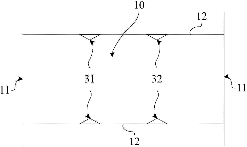
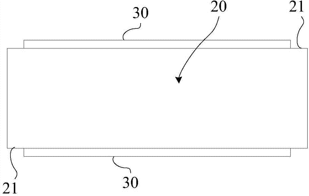
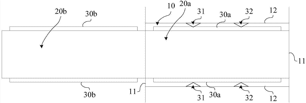
[0033] The battery installation mechanism in the embodiment of the present invention includes such as Figure 1a tank 10 as shown, and as Figure 1b The battery 20 shown, wherein the slot 10 is used to accommodate a battery 10, and:

[0034] See Figure 1a , the groove 10 has two end faces 11 opposite to each other, and two side faces 12 connected between the two end faces 11 and opposite to each other; Opening, the two sides 12 have two pairs of metal contacts 31 and 32 for electrical connection with the battery 20;

[0035] The battery 20 has two mating surfaces 21 for contacting and mating with the two sides 12 of the groove 10; wherein, the two mating surfaces 21 have metal strips 30 for realizing the aforementioned electrical connection by contact...


PUM


Abstract

The invention discloses a battery installation mechanism and electronic equipment. The battery installation mechanism provided by the invention comprises a battery and a slot used for containing the battery; the slot has two end surfaces which are opposite to each other, and two side surfaces which are connected between the two end surfaces and are opposite to each other; wherein the two end surfaces have openings for the battery to be pushed into or out of the slot, and the two side surfaces have at least two pairs of metal contacts used for being in electrical connection with the battery; the battery has two matching surfaces used for being in contact matching with the two side surfaces of the slot; wherein the two matching surfaces have a metal strip used for achieving the electrical connection by contacting with the metal contacts. When the battery needs to be replaced, the battery contained in the slot is pushed out by a battery newly pushed into the slot, and all pairs of metal contacts are switched to contact with a metal strip of the battery newly pushed into slot from contacting with the metal strip of the battery pushed out of the slot sequentially in the process, thereby preventing all the metal contacts from losing the electrical connection with the battery simultaneously, and ensuring that the replacement of the battery cannot lead to shutdown of the electronic equipment.

Description

technical field [0001] The invention relates to battery installation technology, in particular to a battery installation mechanism and an electronic device using the battery installation mechanism. Background technique [0002] For various existing electronic devices powered by batteries (such as mobile terminal devices), the electronic devices must be turned off before replacing the batteries. This causes the standby time of the electronic device to be limited by the single capacity of the battery. Contents of the invention [0003] In view of this, the present invention provides a battery installation mechanism and an electronic device using the battery installation mechanism. [0004] A battery installation mechanism provided by the present invention includes: [0005] The groove has two end faces opposite to each other, and two side faces connected between the two end faces and opposite to each other; wherein, the two end faces have a the opening of the slot, both s...

Claims


Application Information

Patent Timeline
IPC IPC(8): H01M2/02H01M2/20H01M4/00H01M50/244H01M50/247H01M50/503
CPCH01M50/20H01M50/50H01M50/572Y02E60/10
Inventor 李涛
Owner BEIJING SAMSUNG TELECOM R&D CENT
Why Eureka
Try Eureka