Long-stroke permanent magnet linear eddy current brake

An eddy current brake, permanent magnet linear technology, applied in the direction of permanent magnet clutch/brake, etc., can solve the problems that the magnetic field size of the permanent magnet eddy current brake cannot be adjusted, and the braking force characteristics cannot take into account high speed and low speed, etc., to shorten the braking distance, The effect of improving system reliability and increasing braking force density

Active Publication Date: 2015-07-01
HARBIN INST OF TECH
View PDF4 Cites 18 Cited by
  • Summary
  • Abstract
  • Description
  • Claims
  • Application Information

AI Technical Summary

Problems solved by technology

[0004] The purpose of the present invention is to solve the problem that the magnetic field size of the existing permanent magnet eddy current brake cannot be adjusted, and the braking force characteristics cannot take into account both high speed and low speed, and provides a long stroke permanent magnet linear eddy current brake

Method used


Image

  • Long-stroke permanent magnet linear eddy current brake
  • Long-stroke permanent magnet linear eddy current brake
  • Long-stroke permanent magnet linear eddy current brake

Examples


specific Embodiment approach 1

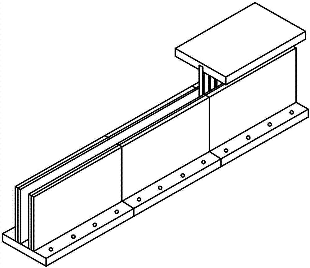
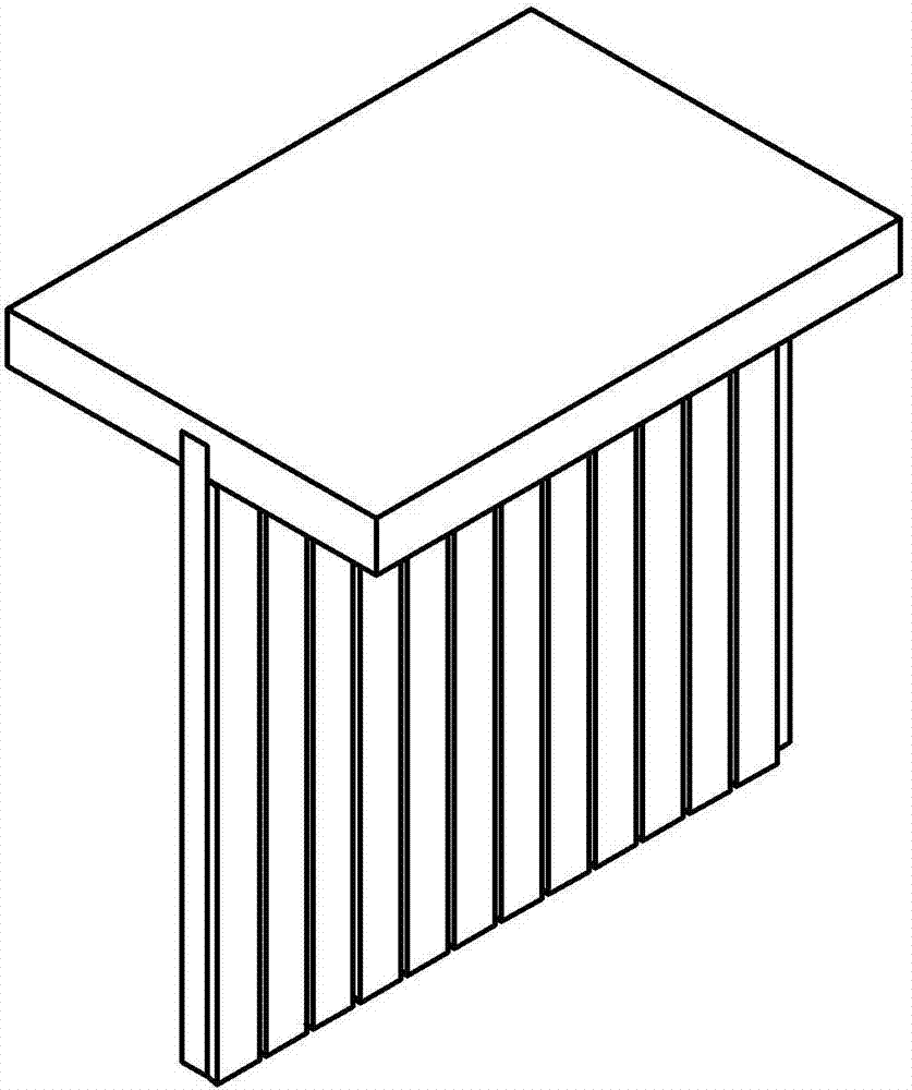
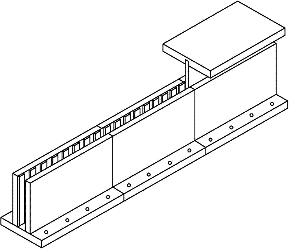
[0030] Specific implementation mode one: the following combination figure 1 , figure 2 and image 3 Describe this embodiment, the long-stroke permanent magnet linear eddy current brake described in this embodiment includes a primary and a secondary, an air gap is formed between the primary and the secondary,

[0031] The primary includes a primary substrate and a primary permanent magnet. The primary substrate is a flat plate, and the strip-shaped primary permanent magnets are evenly arranged along the moving direction of the mover on the side surface of the air gap of the primary substrate. The magnetization direction of all primary permanent magnets is parallel to the primary substrate. , and perpendicular to the moving direction of the mover, the magnetization direction of the adjacent primary permanent magnet is opposite; the secondary includes a secondary conductor plate, and the secondary conductor plate is a composite material metal plate.

[0032] In this embodiment...

specific Embodiment approach 2

[0033] Specific implementation mode two: the following combination figure 1 and figure 2 Describe this embodiment, this embodiment will further explain the first embodiment, the brake is a short primary, long secondary structure, the primary is the mover; the secondary conductor plate is made of a composite metal material with electrical conductivity and metal permeability. A metal plate made of composite material, the electrical conductivity of the secondary conductor plate increases uniformly from the head end to the end, and the head end is the end corresponding to the starting position of the mover.

[0034] The secondary conductor plate is a composite metal plate made of metal materials with different electrical conductivity and magnetic permeability. During braking, as the speed of the mover decreases, the conductivity of the secondary conductor plate material gradually increases.

specific Embodiment approach 3

[0035] Specific implementation mode three: the following combination figure 1 and figure 2 Describe this embodiment, this embodiment will further explain Embodiment 1, the brake is a short primary, long secondary structure, the primary is the mover; the secondary conductor plate is superimposed by a high electrical conductivity metal plate and a high magnetic permeability metal plate The high-conductivity metal plate is close to the air gap side, and the thickness of the high-conductivity metal plate increases uniformly from the head end to the end, and the head end is the end corresponding to the starting position of the mover.

[0036] During the braking process, the thickness of the high-conductivity metal plate gradually increases as the speed of the mover decreases.


PUM


Abstract

The invention relates to a long-stroke permanent magnet linear eddy current brake, belongs to the technical field of motors and aims at solving the problems of an existing permanent magnet linear eddy current brake that a size of the magnetic field cannot be adjusted, and a high speed and a lower speed cannot be considered for the same time for the braking force characteristic. The long-stroke permanent magnet linear eddy current brake comprises a primary level part and a secondary level part between which an air gap is formed; the primary level part comprises a primary substrate and primary permanent magnets, wherein the primary substrate is of a flat plate type; the surface of the air gap side of the primary substrate is provided with the strip-shaped primary permanent magnets uniformly along a rotor movement direction; the magnetizing direction of each primary permanent magnet is parallel to the primary substrate and vertical to the rotor movement direction, and the magnetizing directions of the every two adjacent primary permanent magnets are opposite; the secondary level part comprises a secondary conductor plate which is a composite metal plate. The long-stroke permanent magnet linear eddy current brake serves as an eddy current brake.

Description

technical field [0001] The invention relates to a long-stroke permanent magnet linear eddy current brake, which belongs to the technical field of motors. Background technique [0002] Permanent magnet eddy current braking is a new type of braking technology developed in the 1990s. It uses the strong eddy current generated by the conductor moving in the permanent magnet array and the interaction between the eddy current magnetic field and the permanent magnet magnetic field for braking. There is no friction and no contact during the braking process, and the external environment has no effect on the braking effect. Permanent magnet braking requires no external energy, no noise, no vibration, no pollution, weather resistance, and no wear during braking. It is a green, environmentally friendly, and highly reliable braking technology. It has gradually become the field of braking technology. New directions for research development. [0003] Compared with electromagnetic eddy cur...

Claims


Application Information

Patent Timeline
Patent Type & Authority Applications(China)
IPC IPC(8): H02K49/10
Inventor 寇宝泉张赫张鲁金银锡尹相睿
Owner HARBIN INST OF TECH
Why Eureka
Try Eureka