System for reverse shoulder implants

A reverse, insert technology, used in shoulder prostheses, which can solve problems such as bone loss in patients, difficulty in removing surgeons, etc.

Active Publication Date: 2015-07-01
STRYKER EUROPEAN OPERATIONS LIMITED
View PDF6 Cites 12 Cited by
  • Summary
  • Abstract
  • Description
  • Claims
  • Application Information

AI Technical Summary

Problems solved by technology

Removing an anatomical device that has been integrated into the patient's bony anatomy can often be difficult for the surgeon and can potentially result in excessive loss of the patient's bone

Method used


Image

  • System for reverse shoulder implants
  • System for reverse shoulder implants
  • System for reverse shoulder implants

Examples


Embodiment Construction

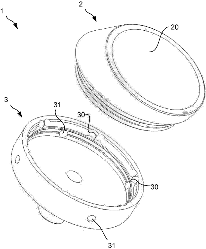
[0119] figure 1 An exploded perspective view illustrating an assembly 1 of a tray 3 and an insert 2 according to an embodiment of the invention. Assembly 1 forms part of a reverse shoulder prosthesis. In implanting this reverse shoulder prosthesis, the humeral head is resected and the stem is implanted into the resected end of the humerus. The tray 3 is coupled with the handle and the insert 2 is coupled with the tray 3 . Since various types of inserts 2 can be used with the tray 3 , for example inserts of different shapes, sizes and / or inclinations, once the desired insert 2 is selected, the insert 2 engages the tray 3 in a snap-fit ​​configuration. connect. Insert 2 may include an articular surface 20, such as a female articular surface 20 configured to receive and abut a male prosthetic head piece or other head piece for articulation therewith.

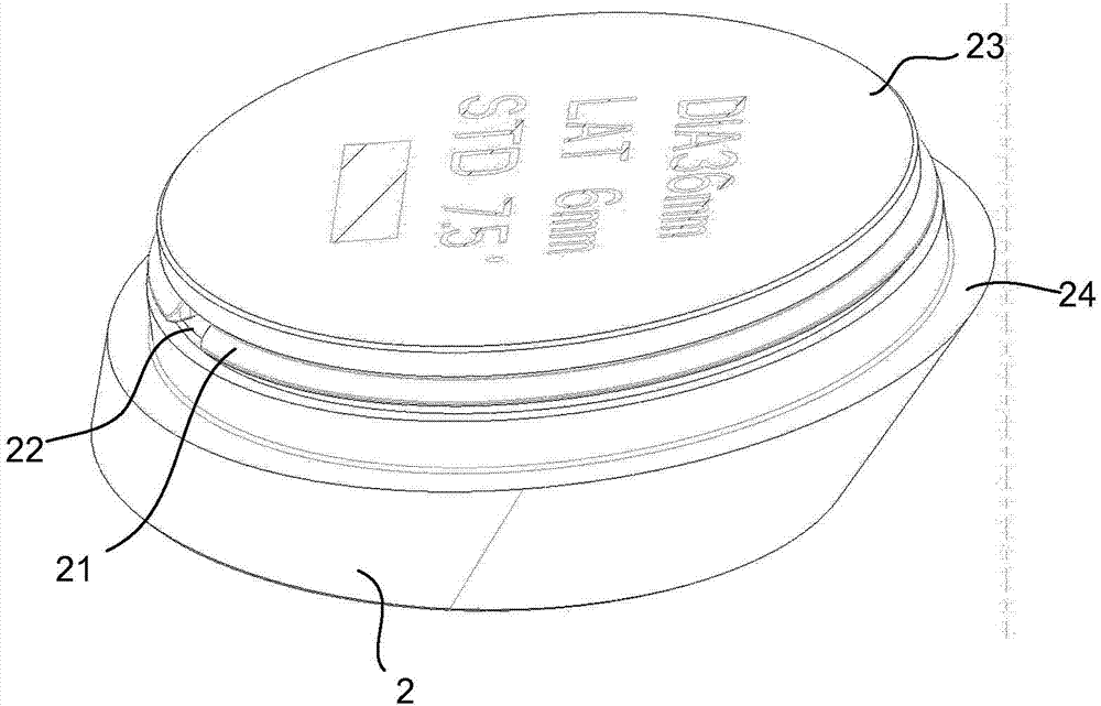
[0120] figure 2 A bottom perspective view of an insert 2 according to an embodiment of the invention is illustrated. imag...


PUM


Abstract

Embodiments of the present invention include a convertible prosthesis that is capable of conversion from a humeral head replacement to a reverse reconstruction without any removal of parts integrated into the patient's bony anatomy (e.g. implant stems). A desired overall implant inclination angle may be achieved by matching various implant stems with various reverse inserts, thus permitting a resection surface to be matched with an implant stem selection while also permitting a desired overall implant inclination angle to be achieved through the selection of an appropriate insert.

Description

[0001] Cross References to Related Applications [0002] This application claims the benefit of US Provisional Patent Application Serial No. 61 / 719,835, filed October 29, 2012, which is hereby incorporated by reference in its entirety for all purposes. technical field [0003] Embodiments of the present invention relate generally to shoulder prostheses, and more specifically to reverse shoulder prostheses. Background technique [0004] Arthroplasty is the standard of care used to treat shoulder arthritis. Typical humeral head replacements that attempt to mimic anatomical conditions involve metal humeral stem and modular head replacements that can be used in multiple positions for optimal bone coverage. This humeral head replacement may articulate with natural bone or an opposing glenoid surface rekeying device, which may be fabricated from UHMWPE or any other acceptable material. Such humeral stems are often provided at one or several inclinations in the range of 125° to 1...

Claims


Application Information

Patent Timeline
Patent Type & Authority Applications(China)
IPC IPC(8): A61F2/40A61F2/30
CPCA61F2002/30332A61F2002/30354A61F2002/30505A61F2002/30604A61F2002/30367A61F2002/4022A61F2002/30616A61F2002/30495A61F2/4014A61F2002/30485A61F2/30A61B17/56A61F2002/3083
Inventor 皮耶里克·德兰萨尔文森特·加博里布莱恩·马罗尼布莱恩·C·霍多雷克肖恩·加加奇帕斯卡·布伊洛吉勒斯·瓦尔希卢奇·法瓦尔菲利普·克拉韦特弗朗索瓦·西尔沃詹姆斯·凯利苏曼特·克里希南德尼埃尔·莫尔塞德里克·科姆特埃里克·伦德斯塔德勒弗朗索瓦·蒙迪
Owner STRYKER EUROPEAN OPERATIONS LIMITED
Why Eureka
Try Eureka