Constant power output circuit and ultrasonic tooth cleaner constant power control method

A constant power, output circuit technology, applied in the electrical field, can solve problems such as output power fluctuations, achieve the effects of solving output power fluctuations, good cleaning effect, and improving adjustment speed

Active Publication Date: 2015-07-08
GUILIN WOODPECKER MEDICAL INSTR
View PDF8 Cites 4 Cited by
  • Summary
  • Abstract
  • Description
  • Claims
  • Application Information

AI Technical Summary

Problems solved by technology

[0003] The technical problem to be solved by the present invention is to provide a constant power output circuit and a constant power control method of the ultrasonic scaler, which solves the defect of the output power fluctuation of the scaler during the working process, so that the working tip of the scaler can be kept optimal The working state of the tooth can achieve better cleaning effect and improve the efficiency of tooth cleaning

Method used


Image

  • Constant power output circuit and ultrasonic tooth cleaner constant power control method
  • Constant power output circuit and ultrasonic tooth cleaner constant power control method

Examples


Embodiment 1

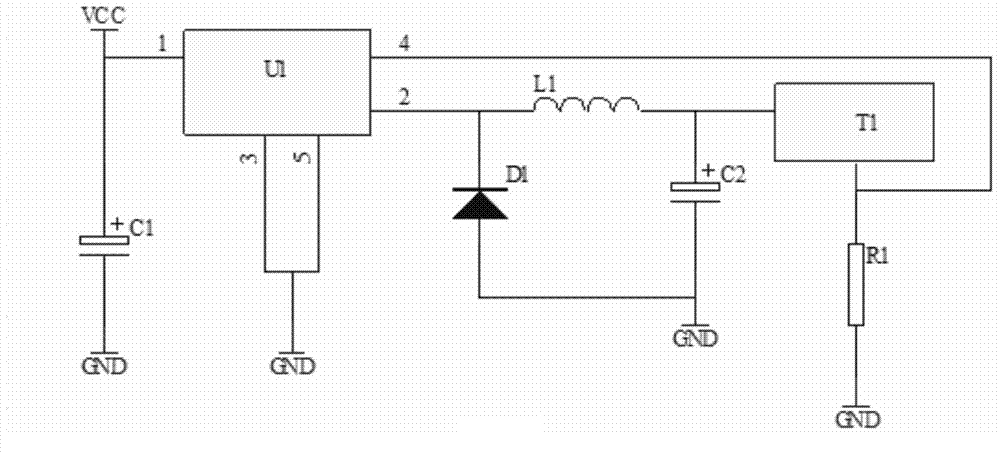
[0018] Embodiment 1, a kind of constant power output circuit, will combine below figure 1 A constant power output circuit provided in this embodiment will be described in detail.

[0019] Such as figure 1 As shown, a constant power output circuit diagram, including power output circuit, sampling resistor R1 and ultrasonic transformer T1.

[0020] The power output circuit includes a voltage stabilizing chip U1 and an inductor L1, the No. 1 pin of the voltage stabilizing chip U1 is connected to an external power supply, and the No. 2 pin of the voltage stabilizing chip U1 is connected to the ultrasonic transformer T1 through the inductor L1 The input terminal, No. 3 pins and No. 5 pins of the voltage stabilizing chip are respectively connected to the ground, No. 4 pins of the voltage stabilizing chip are grounded through the sampling resistor R1, and the output terminal of the ultrasonic transformer T1 is connected to the ground through the sampling resistor R1 is grounded.

...

Embodiment 2

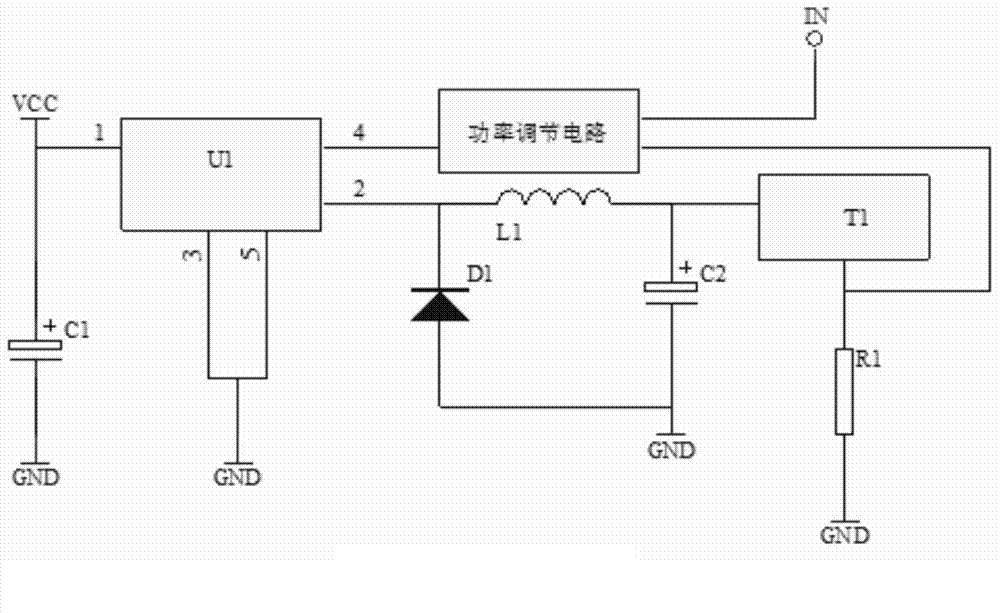
[0029] Embodiment 2, a constant power control method of an ultrasonic dental scaler, will be combined below figure 2 A method for controlling constant power of an ultrasonic dental scaler provided in this embodiment will be described in detail.

[0030] A constant power control method of an ultrasonic dental scaler, comprising:

[0031] Step 1: the voltage stabilizing chip U1 in the power output circuit provides power for the ultrasonic transformer T1 through the inductor L1;

[0032] Step 2: The ultrasonic transformer T1 adjusts the feedback voltage at its output terminal according to the input voltage provided by the power supply output circuit;

[0033] Step 3: The sampling resistor R1 acquires the feedback voltage at the output terminal of the ultrasonic transformer T1 and feeds it back to the voltage feedback terminal of the voltage stabilizing chip U1 in the output circuit of the power supply;

[0034] Step 4: The voltage stabilizing chip U1 in the power output circui...


PUM


Abstract

The invention relates to a constant power output circuit and an ultrasonic tooth cleaner constant power control method. The constant power output circuit comprises a power output circuit, a sampling resistor R1 and an ultrasonic transformer T1. The power output circuit comprises a voltage stabilization chip U1 and an inductor L1, a first pin of the voltage stabilization chip U1 is connected to an external power source, a second pin of the voltage stabilization chip U1 is connected to the input end of the ultrasonic transformer T1 through the inductor L1, a third pin and a fifth pin of the voltage stabilization chip U1 are connected with the ground respectively, the fourth pin of the voltage stabilization chip U1 is connected to the ground through the sampling resistor R1, and the output end of the ultrasonic transformer T1 is connected to the ground through the sampling resistor R1. The constant power output circuit and the ultrasonic tooth cleaner constant power control method achieve the constant power output of a tooth cleaner, the adjusting speed of the power output of the tooth cleaner is improved, a better cleaning effect is achieved, and the tooth cleaning efficiency is improved.

Description

technical field [0001] The invention relates to the field of electricity, in particular to a constant power output circuit and a constant power control method for an ultrasonic dental scaler. Background technique [0002] The principle of the ultrasonic scaler is to use the working tip of ultrasonic vibration to contact the surface of the tooth, and achieve the purpose of removing tartar and plaque on the surface of the tooth through physical methods. Ultrasonic tooth scalers need to use ultrasonic transducers to convert electrical energy into mechanical energy of ultrasonic vibrations. In order to obtain better cleaning results, the tooth scaler needs to output stable vibration power to improve tooth cleaning efficiency. For this reason, it is necessary to develop a scaler with constant power output, so that the scaler can output stable power and achieve better cleaning effect. Contents of the invention [0003] The technical problem to be solved by the present invention...

Claims


Application Information

Patent Timeline
Patent Type & Authority Applications(China)
IPC IPC(8): A61C17/20
CPCA61C17/20
Inventor 吴勋贤陈泽荣林剑华
Owner GUILIN WOODPECKER MEDICAL INSTR
Why Eureka
Try Eureka