

Heavy duty pneumatic tire
一种充气轮胎、重载荷的技术,应用在轮胎零部件、轮胎胎面/胎面花纹、运输和包装等方向
- Summary
- Abstract
- Description
- Claims
- Application Information
AI Technical Summary
Problems solved by technology
Method used
Image

Examples
no. 1 approach
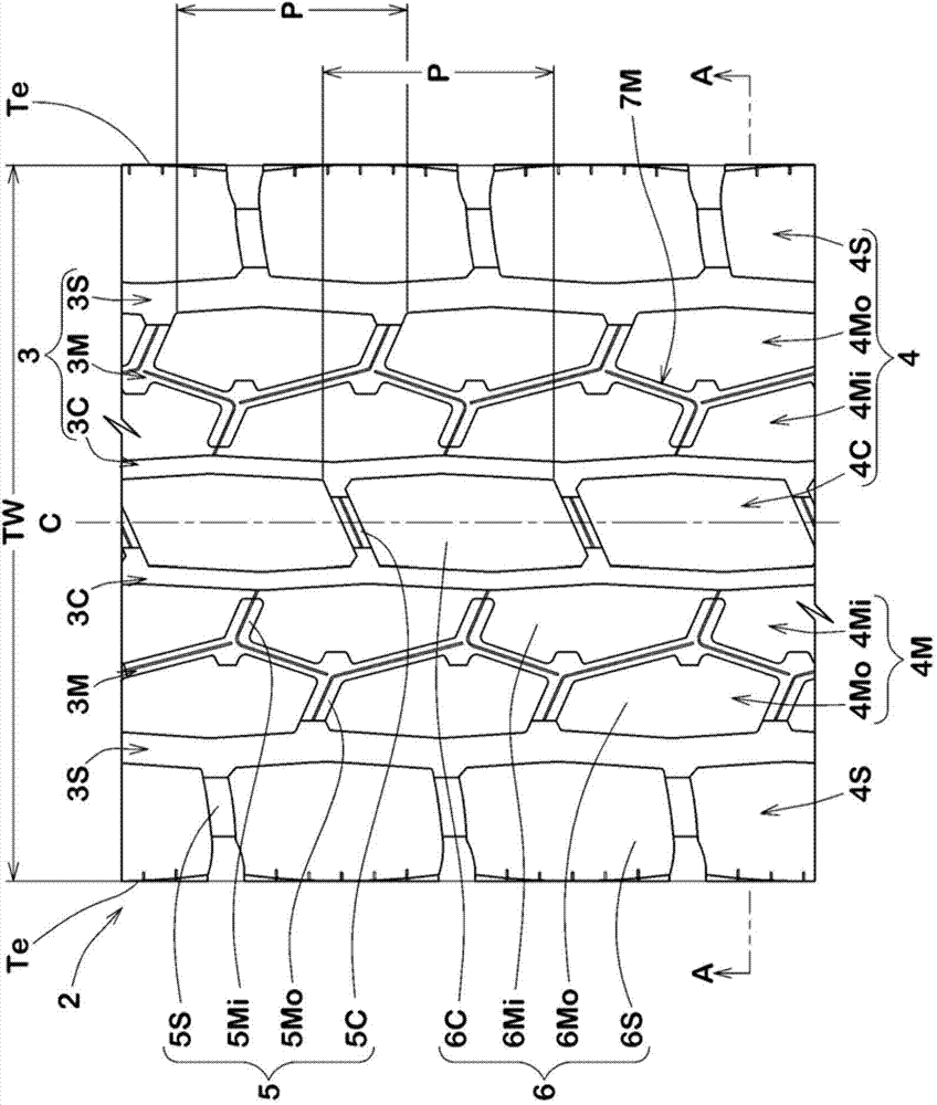
[0043] exist figure 1 2 shows a developed view of the tread portion 2 of the heavy duty pneumatic tire (hereinafter, may be abbreviated as “tire” in some cases) according to the present embodiment.
[0044] Such as figure 1 As shown, a plurality of circumferential main grooves 3 are provided in the tread portion 2 . The circumferential main grooves 3 in this embodiment extend continuously in a zigzag shape along the tire circumferential direction.
[0045] In the present embodiment, the circumferential main groove 3 includes at least one crown main groove 3C, a pair of middle main grooves 3M, and a pair of shoulder main grooves 3S.
[0046] A crown main groove 3C is provided on both sides of the tire equator C respectively. Each shoulder main groove 3S extends at a position closest to the tread edge Te. Each middle main groove 3M extends between the crown main groove 3C and the shoulder main groove 3S. Thus, a plurality of land portions 4 are defined in the tread portion 2 ...
no. 2 approach
[0089] Next, based on Figure 8 A second embodiment of the present invention will be described. In the description of the second embodiment, it should be noted that the same reference numerals are attached to the same or common elements described in the first embodiment, and detailed description thereof will be omitted.
[0090] Figure 8 A developed view showing the tread portion 2 of the second embodiment, Figure 9 show Figure 8 The partial enlarged view of the E-E line section of , Figure 10 show Figure 8 A partial enlarged view of the vicinity of the middle land in Figure 11 show Figure 10 An enlarged view of the F-F line section of . also, Figure 10 The cross-sections of the BB line, CC line and D-D line in the Figure 5 , Figure 7 as well as Figure 6 shown in .
[0091] Such as Figure 8 ~ Figure 10 As shown, in the present embodiment, the first connecting portion 10 and the second connecting portion 11 are provided in the middle main groove 3M.
...
no. 3 approach
[0105] exist Figure 15 ~ Figure 18 A third embodiment of the present invention is shown in . In the description of the third embodiment, it should be noted that the same or common elements described in the first embodiment and the second embodiment are assigned the same reference numerals, and detailed description thereof will be omitted.
[0106] Figure 16 show Figure 15 J-J line sectional view of the tread portion 2 in . Such as Figure 16 As shown, the tire of the present embodiment includes: a carcass 14 ; and a belt layer 15 disposed outside the carcass 14 in the tire radial direction.
[0107] The carcass 14 has a carcass ply 14 a extending from the tread portion 2 to the bead portion (not shown) via the sidewall portion 13 . The carcass 14 in this embodiment is constituted by, for example, one carcass ply 14a. The carcass ply 14a includes, for example, a plurality of carcass cords arranged obliquely at an angle of 80° to 90° with respect to the tire circumferen...
PUM
 Abstract
Description
Claims
Application Information